Hi,
Myself and a buddy have remade some old boards. The RTC on the 25year old original boards doesn't seem to be great often losing its time and date.
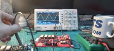
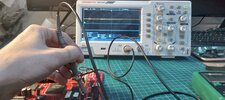
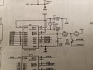
Initially on our remake boards I couldn't get the 32.768khz clock signal using new crystal resonators... I worked out that my oscillating caps (22pf on the schematic) are overloading the crystal. I Fitted an existing crystal from an original old board and it worked... although it has stopped briefly in cold weather.
Using the new crystals with 4pf and 12.5pf I still couldn't get the new crystals to resonate.
This should be an easy job because it's a small circuit... I think I'm missing something...
The PIC RTC is on a socket and works in old boards... Is there anything that the PIC RTC or Vbat circuit can do to mess up the clock out (xtal)? I'm measuring around 4v at the oscillating cap.


