hadoque
New Member
Hi
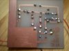
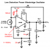
I'm very new to electronics, and I thought a fitting first project would be a Wien-bridge oscillator. Since I have a lm386 amplifier lying around, I thought I'd use the circuit discribed in the datasheet of this component (attached, see page 5). Now I have some questions about this diagram.
What is RL?
What is the "Bypass"? What voltage should I use and where do i connect the output (speaker or whatever)?
Many thanks for help with answering these probably simple questions.