Continue to Site

Welcome to our site!

Electro Tech is an online community (with over 170,000 members) who enjoy talking about and building electronic circuits, projects and gadgets. To participate you need to register. Registration is free. Click here to register now.

  • Welcome to our site! Electro Tech is an online community (with over 170,000 members) who enjoy talking about and building electronic circuits, projects and gadgets. To participate you need to register. Registration is free. Click here to register now.

Wien-bridge oscillator questions

Status
Not open for further replies.
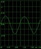
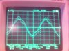
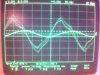
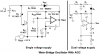
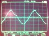
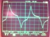
alright, I'm considering this project as finished now. To find a sine wave, i put a potentiometer sreial to the bulb. There was a very small interval, around 15 ohms, that gave the sine wave. I think i could get an even better result pinpointing the correct resistance even better.

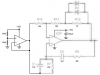
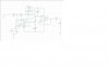
I went back to the original resistors, since I had a hard time finding a sine with audiogurus modification. I also skipped the extra capacitator, since it didn't change the wave at all. I used a 4,5 Volt power source instead of the 9 volt, since the higher voltage gave an output that would smoke my sound card.
so, summing this up:
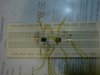
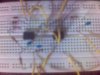
Instead of the specified bulb I used a 6V 40mA bulb with a 15 ohm resistor and i used a 4,5 volt power source.

thanks for the help, again.
 

Attachments

  • 3.jpg
    3.jpg
    34.7 KB · Views: 562
Wien Bridge oscillator problem

i'm constructing this wien bridge oscillator according to the circuit attached.
i wan to generate a 4kHz sine wave

R1=R2=40kohm
C1=C2=1nF (light blue color stating 102 without polarity)
R10=10kohm
R11=18kohm
R12= 5kohm
Diode= 4014
op-amp = HA177241

i tried it with pin 7 and pin 4 of op-amp to be +15V and -15V DC supply with -15V point is short circuit to the GND point.

but i cant seem to get oscillations at all...i dont understand why.
the output is a DC voltage.

can help?
 

Attachments

  • forumgif.jpg
    forumgif.jpg
    36.8 KB · Views: 500
Ivanseng,
The black background on your schenatic is horrible. I made it black and white and inverted it, then boosted the contrast until the JPG artifacts show too much.

Your circuit is baised for a dual polarity supply. It won't work without the negative supply. The common of each supply must be connected to ground.

It can be changed to use only a positive supply if another opamp is used to make a low impedance reference that is half the supply voltage and connects to the two ground points in your circuit.
 

Attachments

  • forumgif.PNG
    forumgif.PNG
    62.1 KB · Views: 481
Sorry about the schematic...i'm lousy pc-user. anyway thanks for replying.

erm..a Flextronic DC supply cannot give a -15V ?

cause normally the DC supply got three points where by [like i shown in the attached image] there is negative point, GND point and a positive point.

is there any other error than what i have given in the schematic? cause i'm testing this circuit in lab. i having a tough time online and reply here. if can i want to know more about what to be done if it still doesnt work.
 

Attachments

  • 11111.JPG
    11111.JPG
    26.8 KB · Views: 401
Your power supply is correct with positive, negative and ground outputs.
Your circuit should work fine with it.

The resistors must be 5% tolerance or lower.
The 1nF capacitors should also be 5% tolerance or lower.
I never heard of your opamp, it might be a 741 which is fine.
The oscillator cannot drive a speaker, its load must be 2k ohms or higher.

Try changing the 5k resistor to 10k.
 
So you mean my DC supply which i inserted to the op-amp is -15V to pin 4 is correct?

my op-amp is a 741 op amp, i juz writing out the name of it, maybe different manufacturer op-amp is different, i do not know, so might as well give the info.

if capacitor i used doesnt have polarity will it still work?
and why is it a DC voltage as output? can explain abit?
 
oh ya regrading the schematic u show me....the second opamp you sugeested... the +15V is to which pin of the opamp? 7 or 4

and is diff diode will give me problem in my output?
 
You should have looked at the datasheet for the 741 opamp before you connected the positive and negative supplies.
If they were connected wrong then the 741 is fried and is destroyed. Replace it.

1nF capacitors do not have a polarity.
 

Attachments

  • 741 opamp.PNG
    741 opamp.PNG
    9 KB · Views: 1,123
thank for replying

Thanks audio guru.

i finally get the ocsillator working. But it has a lot of ripples. From my supervisor, he said i needed a low pass filter about 4kHz.

The picture attached is the result i get from the oscillscope.

and i wanted to ask
1. how do i make a phase shift ? a series of RC circuit is sufficient?
2. Why the output from the series RC circuit is much lower voltage than the output from the wein bridge?
3. between the oscillator and the series of RC circuit, i put a Buffer( voltage follower using an op amp), will it differ?
4. That day audioguru ask to change my 5kohm R to 10kohm R for the speaker? but that will alter the gain of oscillator, is it ok?
5. i try to put a speaker in the series RC circuit between the R and the C, why there is no sound?
6. How to calculate the phase shift? any equation?
7. Any other way of reducing the ripples so that i can get a clean sine wave?
 

Attachments

  • own circuit.jpg
    own circuit.jpg
    111.7 KB · Views: 481
  • with RC phase shift.jpg
    with RC phase shift.jpg
    118.6 KB · Views: 473
  • lala.jpg
    lala.jpg
    93.3 KB · Views: 333
  • DSC00890.jpg
    DSC00890.jpg
    77.1 KB · Views: 355
  • Picture(1).jpg
    Picture(1).jpg
    85.7 KB · Views: 342
Last edited:
Post the circuit you've made, exactly as you've made it - a wein brudge oscillator is a VERY easy circuit to make, and it gives excellent results. You don't require a filter after it as it's a high quality sinewave, if designed and built correctly.

As you've already been told, you can't feed a speaker from a low power oscillator - you need a power amplifier between them.
 
A wien bridge oscillator normally produces a very clean sine wave with only very small distortion. If you're getting anything less than that you're doing something wrong.

I agree with Nigel - show us what you've done.

Brian
 
It looks like the output level is bouncing, also called "squegging".
Maybe the power supply is not regulated and so it is bouncing up and down with the signal.
Maybe the old 741 opamps are too slow and have too much phase shift for a 4kHz output. Then try 10nF capacitors for a frequency of 400Hz.

This Wien Bridge oscillator uses clipping diodes to control the output level. They cause substantial distortion at the top and bottom of the sine-waves.
 
If the oscillator is only being built for educational use, you can get away without any agc at all. You can leave the diodes out and use a variable resistor (decade box is better) to trim until it goes into oscillation.

Brian
 
If you reduce the gain (increase R5) until it just oscillates reliably, the waveform will be less distorted.
 
if i dont want to use the clipping diodes, what can i used other than clipping diodes to overcome this distortion? Power Supply i taken from a Flextronic DC supply source, will it still not regulated?
 
ivanseng said:
if i dont want to use the clipping diodes, what can i used other than clipping diodes to overcome this distortion? Power Supply i taken from a Flextronic DC supply source, will it still not regulated?

There are many different methods, but the clipping diodes is probably the easiest?, although it doesn't offer particularly low distortion - but nothing you could see on a scope!.
 
Texas instruments show two Wien bridge oscillators with a FET for automatic-gain-control. The distortion is less than 0.2%.
If half the FET's drain signal is fed to the gate then the distortion is much less.
 

Attachments

  • Wien bridge oscillator with FET AGC.PNG
    Wien bridge oscillator with FET AGC.PNG
    22.8 KB · Views: 1,696
Last edited:
today i went on to try to increase gain.

this is what i get.

any idas what happening?
 

Attachments

  • normal 3.3 gain.jpg
    normal 3.3 gain.jpg
    111 KB · Views: 421
  • increase gain.jpg
    increase gain.jpg
    114.9 KB · Views: 493
Last edited:
It is clipping and it has a highpass filter feeding a load.

The clipping will cause the top and bottom of the wavform to be flat.
The highpass filter causes the flat top and bottom to be curved and shifted on a diagonal toward the right side.

What is its load?
Measure the output without a load and the clipped top and bottom will be flat.
 
Why did you increase gain? Optimum waveform is achieved when loop gain == 1. As you increase gain a Wien bridge oscillator will increase distortion.
 
Status
Not open for further replies.

Latest threads

New Articles From Microcontroller Tips

Back
Top