Hello,
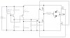
I'm trying to design an H-bridge to control a bank of three motors on a 6-wheel robot vehicle. The direction of the motors is controlled by a signal line which is high for forward and low for reverse. In the attached schematic, the direction signal line is represented via two-position switch, which connects to both a pnp and an npn transistor. The idea (at least in my head) is that when the signal line is high, the npn will conduct, turning on two of the n-channel MOSFETS in the bridge and, when the signal line is low, the pnp will conduct, turning on the other two MOSFEST. In the attached schematic, the motor is represented by two LEDs and a resistor (so I can see which way current is flowing for testing).
What happens is this;
Signal line high: npn conducts, pnp doesn't conduct, the MOSFETS seem to partially switch, but the LEDs don't turn on
Signal line low: npn and pnp both don't conduct
I've clearly fundementally misunderstood this circuit, but I can't see why Any wiser minds prepared to explain what I'm doing wrong would be greatly appreciated...
Thanks,
NFI
p.s. I forgot to say - I tried to build this circuit as well as simulate it and I get the same result: components used were: npn: ZTX302
pnp: ZTX500
MOSFETS: IRF520A
I'm trying to design an H-bridge to control a bank of three motors on a 6-wheel robot vehicle. The direction of the motors is controlled by a signal line which is high for forward and low for reverse. In the attached schematic, the direction signal line is represented via two-position switch, which connects to both a pnp and an npn transistor. The idea (at least in my head) is that when the signal line is high, the npn will conduct, turning on two of the n-channel MOSFETS in the bridge and, when the signal line is low, the pnp will conduct, turning on the other two MOSFEST. In the attached schematic, the motor is represented by two LEDs and a resistor (so I can see which way current is flowing for testing).
What happens is this;
Signal line high: npn conducts, pnp doesn't conduct, the MOSFETS seem to partially switch, but the LEDs don't turn on
Signal line low: npn and pnp both don't conduct
I've clearly fundementally misunderstood this circuit, but I can't see why
Any wiser minds prepared to explain what I'm doing wrong would be greatly appreciated...Thanks,
NFI
p.s. I forgot to say - I tried to build this circuit as well as simulate it and I get the same result: components used were: npn: ZTX302
pnp: ZTX500
MOSFETS: IRF520A
Attachments
Last edited: