Continue to Site

Welcome to our site!

Electro Tech is an online community (with over 170,000 members) who enjoy talking about and building electronic circuits, projects and gadgets. To participate you need to register. Registration is free. Click here to register now.

  • Welcome to our site! Electro Tech is an online community (with over 170,000 members) who enjoy talking about and building electronic circuits, projects and gadgets. To participate you need to register. Registration is free. Click here to register now.

Why does my current mirror not work

Status
Not open for further replies.

turbo_henky

New Member
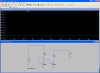
I want to make a current mirror. I did do some simulations and that works, but when I make a real current mirror this does not work. I made the current mirror also with R1=150R so I=28mA, but then the current in R3 is as follow with different resistor values:
R3=100R I=34mA
R3=56R I=41mA
R3=47R I=44mA
R3=33R I=48mA
R3=22R I=52mA
R3=10R I=57mA
R3=5R I=61mA

What am I doing wrong?

I did use a BC548B and simulate with a BC548C, but that should not matter. I also tried other transistors and the current in R3 is never near the current in R1
 

Attachments

  • current-mirror-simulation.JPG
    current-mirror-simulation.JPG
    100.9 KB · Views: 504
Last edited:
I understand the theory as explained on the link. My simulation is working as expected. Why should I post my simulation file?
My real circuit does not work.
 
I understand the theory as explained on the link. My simulation is working as expected. Why should I post my simulation file?
My real circuit does not work.

If you understand the theory, have you considered that the transistor gain in the real world should be matched in order for the tracking of the two collector currents to match,??

I asked for your asc file so that I could change one the transistor types to another BC with a slightly different gain.... you try it and you find it will not track..
 
I know the gain should match for equal current. But if the gains are a little different, the current through R3 should remain the same while changing the value of R3, Right?

Attached the ASC file.

I also build the circuit with a PBSS4021SN, which has 2 transistors in one package. This configuration does also not work. The current through R3 is increasing when decreasing R3

I hope you can help
 

Attachments

  • current-mirror.asc
    1 KB · Views: 200
Last edited:
I know the gain should match for equal current. But if the gains are a little different, the current through R3 should remain the same while changing the value of R3, Right?

Attached the ASC file.

I also build the circuit with a PBSS4021SN, which has 2 transistors in one package. This configuration does also not work. The current through R3 is increasing when decreasing R3

I hope you can help

hi,
Add a 10R thru 22R into each emitter connection.

Without balancing resistors, its the 'slope' of the mismatched transistor gains that can cause tracking errors.
Thats why your original table of results shows an increasing error.
 
Last edited:
hi,
This shows the effect of the emitter resistors when using different gain transistors.
 

Attachments

  • AAesp01.gif
    AAesp01.gif
    23 KB · Views: 359
OK, I add a 10R resistor to each emitterand now it works much better. Now the current through R1 is 26mA and through R3 is 30mA for any resistor value (lower than 150R). It's not as in the simulation, but this is OK

So it is the difference in Gain that makes it not working? Are there special matching transistors for current mirrors, which can have about 2A for each leg?
 
Eric.. theoretically, yes the gate current, its the gate current you need to set.. the mirror isn't finished until the two transistors are in sync the gate current through the first transistor is fixing the current through R1 but the current flowing into the gate of the second transistor may be a tad higher or lower AS WELL as the gain of the second transistor... So the current flowing from gate to emiter is the one we need to control.

Ian

hi Ian,
This I know...:)

I suspect the OP is trying to get a performance thats not within the range of the mirror.

hi_turbo.
I would be interested in knowing what he is actually using it for...?
 
I actually want to copy the current through en peltier element.

I have a design with one peltier element, which is current controlled with a controller.
Now I want to add a second peltier element to the design. Now I want to copy the current of the first peltier element to the second element.
With this solution I hope I don't have to change the control loop.

That the current are not exactly the same is not a problem I think. The current through the first peltier element now is max 2A

Sounds an interesting problem, which transistor types are you using for the 2Amp.?
 
Last edited:
Status
Not open for further replies.

Latest threads

Back
Top