Continue to Site

Welcome to our site!

Electro Tech is an online community (with over 170,000 members) who enjoy talking about and building electronic circuits, projects and gadgets. To participate you need to register. Registration is free. Click here to register now.

  • Welcome to our site! Electro Tech is an online community (with over 170,000 members) who enjoy talking about and building electronic circuits, projects and gadgets. To participate you need to register. Registration is free. Click here to register now.

what's the type/material of these caps?

Status
Not open for further replies.

xiongyw

New Member
hi,

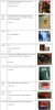
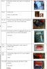
as a newbie in this area, i am trying to get familiar with basic elements (in terms of look and feel at least), so i opened an old PC speaker, and want to know what's inside. attached picture is a list of caps used in the speaker, for some of them, i do not know what type/material of them.

can you please help to identify those caps with question marks? and/or double check the rest?

thanks a lot,
/bruin
 

Attachments

  • caps.JPG
    caps.JPG
    119.3 KB · Views: 213
Read the text comments to the left of the pictures. That says it all.

Go to DigiKey.com or Mouser. They have pictures of the various capacitors they sell.
 
Last edited:
**broken link removed**

C5, C6 are ceramic. Low tolerance, unstable dieelectric which is why they can be so large. 47uF is almost impractically large for most ceramic dieelectrics. I also see no polarity markings which is another indicator since ceramic is unpolarized. The other possibility is tantalum since they can handle the larger capacitances, but i see no polarity markings which are necessary for tantalums.

C7-C8 is ceramic. The stable, accurate, but small capacitance dielectrics.

C102, 104, 105, 106, 201, 202 are the expensive high quality, but low capacitance capacitors. They may be polyester, polypropylene or mica (but I really REALLY doubt it's mica as that stuff is expensive as hell because it makes super good capacitors).

I'm not sure about C11-C12. Could they be the Metallized Polyester Film Capacitors in the link?
 
Last edited:
Contrarary to dknguyens suggestion, I believe that C5 and C6 are 47nF polyester types, not 47uF ceramic.

JimB
 
Last edited:
C7, C8 are ceramic as already mentioned and going from the description of how they're connected are probably used for frequency compensation of an op-amp circuit.

C11, C12 are metal film, probably polyester, 3.3nF.

The descriptions and values for the remaining capacitors (C102 onwards) are correct. They are probably all polypropylene which is common for audio amplifiers like these.

C102, C104 is probably part of a zobel network: there's probably a resistor in series with each capacitor, one for each audio channel.

C201, C202 are a simple crossover, they block bass frequencies which would blow the tweeters.
 
thanks to all for the help (and the correction of two stupid mistake in reading the capacitances).
i attached the updated list of caps, as well as the schematics of the speaker circuit (so it might be clear where the caps were used for).
though i put a lot of efforts in trying to get the schematics as accurate as possible, but their might be also some mistakes. one of my goals, after figuring out the schematics, is to understand the circuit to certain extend, as a way to get familiar with audio DIY subject. so if you can take a look of the schematics, and point out possible faults (doubts), or give brief description of each block, then it will be very helpful.
actually i already have a couple of questions in my mind regarding this circuit:
1. polarized caps in signal coupling: C3/C4 (2.2uF) are used in coupling audio signal from the jackets (A & B) to op-amp chip, and C101/C103 (also 2.2uF) are used in coupling op-amp output signal to LM1875. my question is, how we can tell, in these two cases, that the input end will always has higher voltage (according to the polarization)?
2. it seems the power supply to LM1875 is not regulated, but power supply to OP-amp (NE5532) is regulated. why the difference? is it typical that power amp does not require a regulated power supply?
3. what's the purpose of R11/R12 in PSU (in input of the voltage regulator)? it seems it's to lower the input voltage to the regulator (from 25V to 19V), but how the resistance value is obtained (since i did not find the input impedance spec from the regulator's datasheet)?
4. W1 is supposed to do tone adjustment (related to Bass as the speaker spec tells). What's the effect and how it works? a reference url would also be very helpful.
5. Input Jacket "JA" is supposed to boost the higher frequence, as the speaker spec tells. Why? my guessing is something like this (for right channel): for lower frequencies, the resistance is reaching to the value of R1, while for higher frequencies, the resistance is reaching half of R1 (R1//R5), thus the voltage divided to the load (op-amp) will be more with higher frequency than lower frequencies. is this a correct interpretation?
6. what's the purpose of the relay (JD1/JD2)? as i experienced, when i turn on the speaker, i do not hear noise (i also do not hear the sound from the relays--but may because the power switch is close to the relay). but when i turn off the speaker, there is always a kind of noise (bunnn) from the speaker, and i can hear clear the "tick" from the relays with about 1~2 seconds of delay. why there is a noise when i turn off the power?


i am sorry that i asked too many questions.
thank you again for your help...
/bruin
 

Attachments

  • caps2.JPG
    caps2.JPG
    90.2 KB · Views: 162
  • psu.JPG
    psu.JPG
    27.1 KB · Views: 160
  • opamp.JPG
    opamp.JPG
    39.5 KB · Views: 153
  • poweramp.JPG
    poweramp.JPG
    51.1 KB · Views: 156
1) Polarised capacitors can be used for AC coupling providing the DC bias is higher than the negative peak voltage. For example if you have a capacitor with a 1V DC bias and a 1V peak AC signal the minimum voltage across the capacitor will be 0V and the maximum voltage will be +2V.

2) You're right audio amplifiers don't need a regulated supply. The supply to the NE5532 is regulated because it has an absolute maximum voltage rating of +/-22V so powering it from +/-25V would destroy it.

3) The resistors help to reduce the power dissipated by the regulators. C9 and C10 should really be after the resistors to help improve the quality of the supply to the regulator.

Check the pinout to the LM7912, it looks wrong to me.

4) W1 forms a filter with R9, R10, C5, C6 and W2; it's a dual ganged potentiometer one side is for the left channel and the other is for the right.

Let's just look at one channel for now. The filter relies on two things:

The impedance of a capacitor decreases with increasing frequency.

The impedance of a resistor remains constant regardless of the frequency.

C5 and W1 are connected in parallel.

R9, C5 and W1 and W2 form a potential divider.

As the frequency increases the impedance of C5 decreases, therefore the output of the potential divider with increase with increasing frequency.

W1 damps the effect of C5, the lower W1's setting the less difference C5 makes, therefore W1 must be a bass boost control.

5) You'll get treble boost from JA because C11 and C12 have a lower impedance at higher frequencies.

6) The relays delay connection of the speakers so it doesn't make a thump noise when the power is turned on. I would guess that it makes a small thump noise when it's turned off because the one power rail's filter capacitor will discharge at a slightly different rate to the other rail's causing a small current pulse through the speaker.
 
Thanks for your reply, Hero999!

1) Polarised capacitors can be used for AC coupling providing the DC bias is higher than the negative peak voltage. For example if you have a capacitor with a 1V DC bias and a 1V peak AC signal the minimum voltage across the capacitor will be 0V and the maximum voltage will be +2V.
Understood. so the question is, how we can tell that the DC bias imposed on the coupling cap is a forward bias which is big enough? In this case, for C3/C4 before o-amp input, why the circuit designer can assume that an enough forward bias is there? the input is come from JA or JB, which is connected the output of CD player, or MP3, or sound card. browsing the web, I also noticed the same polarity configuration, e.g., in <http://www.dself.dsl.pipex.com/ampins/webbop/opamp.htm>, all the input coupling caps is polarized the same way. i am guessing this may due to some characteristics of the op-amp chip which i am not familiar with (I will study these in consequence).

2) You're right audio amplifiers don't need a regulated supply. The supply to the NE5532 is regulated because it has an absolute maximum voltage rating of +/-22V so powering it from +/-25V would destroy it.
i also read in some article talking about PSRR of an op-amp, it seems that the basic facts is that the output voltage of an op-amp is also related to the voltage (or change of the voltage) of power supply (in a way related to PSRR somehow). so i guess that might be one of the reasons why op-amp needs a regulated power supply.
For the power-amp, i guess it would be suffice for me at the moment to remember that it does not require a regulated power supply (as compared to op-amp). i will give a closer look of the reasons when it crosses.
3) The resistors help to reduce the power dissipated by the regulators. C9 and C10 should really be after the resistors to help improve the quality of the supply to the regulator.

Check the pinout to the LM7912, it looks wrong to me.
So what would be the common practise in choicing the resistance values (as well as power ratings) of R11/R12, particularly in this case? i.e., why there are 100 ohm in this case?

For C9/C10, thanks for point this out. I will double check the PCB to verify that.
4) W1 forms a filter with R9, R10, C5, C6 and W2; it's a dual ganged potentiometer one side is for the left channel and the other is for the right.

Let's just look at one channel for now. The filter relies on two things:

The impedance of a capacitor decreases with increasing frequency.

The impedance of a resistor remains constant regardless of the frequency.

C5 and W1 are connected in parallel.

R9, C5 and W1 and W2 form a potential divider.

As the frequency increases the impedance of C5 decreases, therefore the output of the potential divider with increase with increasing frequency.

W1 damps the effect of C5, the lower W1's setting the less difference C5 makes, therefore W1 must be a bass boost control.
This is an excelent/detail description, which gives me some insights. i also found another brief comments on this circuit (talking about the same speaker), at <http://bbs.ustc.edu.cn/cgi/bbsanc?path=/groups/GROUP_6/HiFi/D7D414A5B/M.1030306415.A>. Assuming you may be not versed in reading chinese, the translation of the comment "NE5532构成的前置放大器为0db放大器,音调控制旋钮通过一个RC滤波器控制NE5532输出信号的反馈量达到增减低频分量的目的." reads: "the pre-amp by NE5532 is a 0db gain amplifier, followed by the tone control, which is implemented by a RC filter to control the amount of feedback to the op-amp, for boost or damp the bass."
here the "feedback" is mentioned. i guess i also need to get familiar with op-amp to fully understand this.

6) The relays delay connection of the speakers so it doesn't make a thump noise when the power is turned on. I would guess that it makes a small thump noise when it's turned off because the one power rail's filter capacitor will discharge at a slightly different rate to the other rail's causing a small current pulse through the speaker.

By "power rails's filter capacitor", which capacitor you are refering to? C108/C110, or else?


Thanks again,
/bruin
 
Understood. so the question is, how we can tell that the DC bias imposed on the coupling cap is a forward bias which is big enough?
As I said before, the DC bias needs to be equal to the peak negative voltage.

In this case, for C3/C4 before o-amp input, why the circuit designer can assume that an enough forward bias is there? the input is come from JA or JB, which is connected the output of CD player, or MP3, or sound card. browsing the web, I also noticed the same polarity configuration, e.g., in <http://www.dself.dsl.pipex.com/ampins/webbop/opamp.htm>, all the input coupling caps is polarized the same way. i am guessing this may due to some characteristics of the op-amp chip which i am not familiar with (I will study these in consequence).
I haven't read the text on the site you've linked to.

Just looking at the schematics, it appears that non-polarised capacitors should have been used.

Take the fist circuit:

**broken link removed**

The DC voltage as the negative terminals of both capacitors will be 0V.

Assuming the input is just a dynamic microphone and the output is just a resistor connected to 0V, the DC bias on the positive rail will also be 0V.

The same is true for the other circuits.

I therefore conclude that polarised capacitors should be used.

i also read in some article talking about PSRR of an op-amp, it seems that the basic facts is that the output voltage of an op-amp is also related to the voltage (or change of the voltage) of power supply (in a way related to PSRR somehow). so i guess that might be one of the reasons why op-amp needs a regulated power supply.
For the power-amp, i guess it would be suffice for me at the moment to remember that it does not require a regulated power supply (as compared to op-amp). i will give a closer look of the reasons when it crosses.
Power supply rejection ration is how well the op-amp ignores the power supply and doesn't allow it to affect the output.

So what would be the common practise in choicing the resistance values (as well as power ratings) of R11/R12, particularly in this case? i.e., why there are 100 ohm in this case?
The power rating is equal to I²R or V²/R.

In this case R11 and R12 just take the strain off the LM7812.

The nominal input voltage to each regulator is 18√2-1.4V = 24V. This means, without the 100R resistor, it needs to drop 12V, if the output current is 80mA the power dissipation will be 960mW (nearly 1W) which will cause it to overheat without a heatsink. With the 100R resistor the regulator will only have to drop 4V so the power dissipation will only be 320mW.

I haven't calculated the amount of current required from the regulators the above is just an example.

For C9/C10, thanks for point this out. I will double check the PCB to verify that.

By "power rails's filter capacitor", which capacitor you are refering to? C108/C110, or else?
Yes, C108 & C110.
 
Thanks so much for the answers.

As I said before, the DC bias needs to be equal to the peak negative voltage.


I haven't read the text on the site you've linked to.

Just looking at the schematics, it appears that non-polarised capacitors should have been used.

Take the fist circuit:

**broken link removed**

The DC voltage as the negative terminals of both capacitors will be 0V.

Assuming the input is just a dynamic microphone and the output is just a resistor connected to 0V, the DC bias on the positive rail will also be 0V.

The same is true for the other circuits.
I therefore conclude that polarised capacitors should be used.
With this example, I get more concrete feeling about the rules in polarizing capacitors. I will also double check the PCB to verify the polarization of the coupling caps (as well as the GND connections, I guess), then to figure out reasons for that. Sorry I did not have a chance to verify the C9/C10 location (as you pointed out in a previous reply), I should be able to do that during this weekend.
Btw, I guess, in the last sentence of your reply above, "polarized" is a typo of "non-polarized".
In this case R11 and R12 just take the strain off the LM7812.

The nominal input voltage to each regulator is 18√2-1.4V = 24V. This means, without the 100R resistor, it needs to drop 12V, if the output current is 80mA the power dissipation will be 960mW (nearly 1W) which will cause it to overheat without a heatsink. With the 100R resistor the regulator will only have to drop 4V so the power dissipation will only be 320mW.

I haven't calculated the amount of current required from the regulators the above is just an example.
Very helpful example which conveys a lot of information (RMS to Peak, diode voltage drop in rectifier, power dissipation esitmation for ICs, etc) to be grasped and digested. Thanks again for the help, Hero999!
 
Hi, Hero999,

I checked the PCB last night, for the location of C9/C10, you are right, C9/C10 is actually placed after the output pin of the regulators, not before R11/R12. Thanks again for pointing this out.

Btw, about R11/R12, there is about 4V voltage drop on each of them, yileding 40mA current. A typical voltage value before the resistor is 24V, after that it's around 20V, and after the regulaters, it's 12V. I am using a mulitmeter to measure the voltages (with neither input signal nor load), and since the main voltage flucturates (220VAC~230VAC), the values above are just ballpark figures.

Thanks again,
/bruin
 
Last edited:
Status
Not open for further replies.

New Articles From Microcontroller Tips

Back
Top