Continue to Site

Welcome to our site!

Electro Tech is an online community (with over 170,000 members) who enjoy talking about and building electronic circuits, projects and gadgets. To participate you need to register. Registration is free. Click here to register now.

  • Welcome to our site! Electro Tech is an online community (with over 170,000 members) who enjoy talking about and building electronic circuits, projects and gadgets. To participate you need to register. Registration is free. Click here to register now.

What would you want in a PIC development board?

Status
Not open for further replies.

blueroomelectronics

Well-Known Member
If you could design a PIC development PCB...

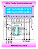
Examples of development boards.
EasyPIC6
LAB-XT

PCB size will affect the cost, so remember smaller is cheaper. I would like it to be either so it can be put into a 2 or 3 ring binder.
It will be a double sided FR4 PCB with top & bottom solder masks and silkscreen on the top layer.
Design goals are to use mostly common readily available parts, also avoiding surface mount for ease of assembly and repair.

Standard features (No built in programmer)
Programming connector ICD2 (RJ12), Junebug/Inchworm (2x5) or PICkit2 (RA 1x6)
2mm coax power jack with bridge rectifier (round or square?)
5V LM7805 or LM2940 regulator
Jumperable USB-B connector & 0.47uF for 18F4550
Crystal socket with jumpers for A6 & A7
16 pin inline 2x16 LCD connector
One 10K pot with jumpers for several I/O configurations
RS232 port with MAX232 (DTE or DCE?)

What onboard features do you consider important for a development board

Space around 40 pin socket to support a ZIF socket
35 LEDs one per Output pin
36 pushbuttons one per Input pin
4x4 keyboard matrix
pushbutton type joystick keypad (as seen on EasyPIC6)
28 pin socket
18 pin socket
8 pin socket
Solderless breadboard, Large, Medium or Small
4.096V voltage reference (not exactly a common part though)
RS485 (SN75176 or MAX485 etc...)
I2C EEPROM
SPI EEPROM
I2C RTC (DS1307) will require battery
2x5 I/O headers (as seen on EasyPIC boards)
128x64 GLCD 20pin header
3pin 1wire connector

Comments
PS I'll edit this post with additional features
 
Bill, I would like a header to all I/O pins for easy connetion to my own BB, maybe a male and female header configuration...
 
Temp sensor sure, which one?
The headers seem to be popular.

Although you state a desire for through-hole only, the SMD TC1047A on a little section of PCB (which can be snapped off) on a PICDEM Mechatronics board is a handy feature. The section is connected by tracks between 2X3 plated through-holes, which allow wires to be used to place the sensor remotely, once the section is snapped off.
 
Hi,

Surely the answer to your question depends on your target market or are you trying to do a catch all type of board ?

If I was buying a dev board as a beginner or advanced user, an onboard programmer /debugger would be essential.
 
1. Dip switches for more flexibility in connecting LEDs, push buttons, pull-up/pull-down resistance to I/O pins.
2. One buzzer.
3. A couple of relays.
4. An MT8870 IC for working on telephone related projects. This would make your board unique of others.
5. 1 Digital to analog Converter.
6. A 3-pin female header for DS1820.

- Raj
Experiments with PIC16F628A
 
I second a piezo sounder as standard.

I'd like header sockets so you could stack an 'options' board on top of the main demo platform. A cut-down Junebug could be one option for beginners, I'd love an ethernet option. Others could be multi channel mains dimmers, low power motor control etc., all the usual stuff that gets asked about on here.
 
Last edited:
Here's what I'd like to do, try to design a development board where it's sold as a bare PCB. (that's why I'm aiming for easy to get parts)
I'd like the size to be either 8.5" x 11" large, or 5.5" x 8" smaller, portable, cheaper.
I would like to cut the fat so to speak, just a big board full of empty sockets seems to be a waste of space.

I have an Ethernet kit on the backburners. It's got a 64pin TQFP so it's beyond the scope of this project.

Motor control has its own power requirements but if there's space it's a possibility, servo control is easy and would just be a couple of three pin jumpers.
As for the 120VAC stuff that'll be a very different project.
 
Last edited:
Hey Bill,

I too have designed a few dev boards, not for commercial purposes, just purely out of frustration at breadboarding regular 'modules'. My designs tend to balloon out of all proportion so I either strip back to basics, or at least have ALL I/O's broken out and labelled, with both single pin header strips, and female ones (mandatory for CPLD and FPGA anyway). ALso its very handy to have a 'aux comms' header which has connections for SPI, I2C and UART - I just use a 10 pin header for that since IDCconnectors are easy to use/find.

Check this out:
**broken link removed**

I have two, one for AVR/PIC's, and one for xilinx/altera CPLD/FPGA's.

If you could make somethign similar to that, but with footprints for PICs (and their respective needs) taht would be awesome.

Making a 'generic board' really is tough, so many deicisons.....

BuriedCode
 
Last edited:
I would think about just making it 40 pin PIC only. That frees up PCB space for gizmos. Most app developments can be done on 40 pin then modded later for a smaller target PIC if needed. Definitely look at a ZIF socket.

Consider making daughterboards that hold smaller PICs that will slot into the 40 pin ZIF. This won't eat into valuable motherbaord real estate and will probably provide accessory sales.

I think compulsory items are text LCD, and LEDs and pushbuttons for every PIC pin, xtal socket, RS232 port and chip, bringing all PIC pins to external header.

High value features; buzzer, adc pot, 3 pin connector for DS1820 and LM335 temp sensors, 74HC595 shift regsiter with 8 parallel outputs.

Cool feature ideas; R2R SIL network to make easy DAC with little real estate needed, 5x7 LED matrix seem to be popular maybe with a ULN2003 to drive it. IR comms, but BOTH directions! Also a large I2C eeprom.
 
what about flash SD card slot ?
 
I like the idea of 40 pin support only.
Space for a ZIF would be worth the real estate.
Would using PORTD,E for LCD 4bit and a 4x4 keypad +11 LEDs be workable?
 
Some suggestions;

(1) A piezo speaker is "a must".
(2) Consider using a small PIC as a serial/i2c 44780 LCD + Keypad + Speaker controller for the most "bang for the buck" on board space and host pins.
(3) Don't dedicate pins on PORTB for "ICSP only" use.

There are plenty of applications that need an entire 8-bit PORTB. Consider for example a little 1-inch high by 6-inch long matrix display using those tiny 0.7-inch 5x7 displays from BG Micro (below).

Regards, Mike
k8lh-7x55-%C2%B5sign-concept-png.34823
 
While using a small PIC for a "serial backpack" type LCD controller would use a more 'standard' software interface it might not fit your "easy to obtain" criteria. How about using a 74HC164 instead for the 2-pin Predko interface? It uses a custom driver but it's cheap and it can be modded to drive half a keypad which would reduce host pin requirements.

More food for thought, Mike
predko-mod-png.34825
 

Attachments

  • Predko Mod.PNG
    Predko Mod.PNG
    28.3 KB · Views: 1,036
I have a different view on those peripherals... The main thing I use a dev board for is to quickly develop things that will later be built as finished hardware to operate self-contained.

So the dev board needs to mimic the final hardware! If you use a 74164 etc to drive the LCD then all the finished hardware devices you build must also use a 74164 and all the extra wiring. I think it's so much better to have the LCD connected to 6 PIC pins on a common port (like PORTB) then all you need to do to make a finished app in hardware is copy the 6 wires that are used on the dev board.

That's also the reason you need a LED for every PIC pin, it doesn't matter what final hardware will be connected to that pin; like a solenoid, light, PWM motor etc, if the dev board has a LED for that pin you can still develop the app completely and you know it will work when built on the final app hardware later. Likewise one pushbutton for each pin.

But then my needs might be different from others, some people might just want like a pic "laboratory" where it is easy to code different demonstrations to learn how the PIC works, test ideas and have fun, rather than as a tool to be used to develop actual applications that will be built.
 
Status
Not open for further replies.

Latest threads

New Articles From Microcontroller Tips

Back
Top