Continue to Site

Welcome to our site!

Electro Tech is an online community (with over 170,000 members) who enjoy talking about and building electronic circuits, projects and gadgets. To participate you need to register. Registration is free. Click here to register now.

  • Welcome to our site! Electro Tech is an online community (with over 170,000 members) who enjoy talking about and building electronic circuits, projects and gadgets. To participate you need to register. Registration is free. Click here to register now.

wein bridge oscillator

Status
Not open for further replies.
You need the gain-setting resistors to cause a gain of slightly less than 3 so the diodes can adjust the output level.
In your circuit with a minimum gain of 3 the opamp output will reach clipping and the diodes will not do anything.
 
Message removed. Poster was confused.

EDIT: I think the equation should be: Vo = 3R1Vd/R3.
 
Last edited:
You need the gain-setting resistors to cause a gain of slightly less than 3 so the diodes can adjust the output level.
In your circuit with a minimum gain of 3 the opamp output will reach clipping and the diodes will not do anything.

does that mean after diode adjustments, the gain will be set back to a maximum value of 3?
 
does that mean after diode adjustments, the gain will be set back to a maximum value of 3?
Yes.
You want the diodes to conduct only a little and only at the peaks of the sine-wave for the lowest amount of clipping distortion from the diodes.

Note that the voltage of the diodes is temperature sensitive so the output level will change a little when the temperature changes.
Note that diodes in a clear case are light sensitive and the output of the oscillator might become modulated by light.
 
Yes.
You want the diodes to conduct only a little and only at the peaks of the sine-wave for the lowest amount of clipping distortion from the diodes.

if the diodes conduct only a little, does that mean there is still some shunt resistance in between the diodes thus increasing the gain back to 3?
how does the resistors know how to auto adjust back to 3 or do i have to use a VR to tune it until the values adjust perfectly..
 
oh and when i simulate conditions R2 less than R1 (without amp stab.) thus making the gain less then 3 where oscillations are supposed to attenuate to nothing..i get a small amount of signals at the beginning in the microvolt range before the signal completely becomes a flat 0...are those micro signals due to noise in the circuit?
 
You should use a trimpot to adjust the gain. If the gain is too high then the circuit turns on quickly but the distortion from the diodes will be high.
If the gain is too low then the circuit will not start oscillating or the output level will rise slowly.
The amount of gain affects the output level a little.
 
qtommer, look at post #26. That setup should work well. AG's comments about gain of 3 were directed at a different oscillator than yours. It confused me too.
 
I am so sorry AudioGuru and BrownOut but im kinda confused now:

Referring to post #26

In this case, when the signal reaches a cetain value, the diodes short out R6, and now the gain is:

1 + (15K + 0/10K) = 2.5. that will stop the signal from growing. In that way, the tops of the signal aren't clipped by hitting the power rail.

so does it mean that after the diode comes into play, the diodes will fully conduct and the shunt resistance is completely shorted out thus leaving the gain below 3?

and once oscillations have started (by setting the gain to higher than 3), the loop gain can then be reduced to even less than 3 and will still continue oscillating?

Therefore, once a signal grows , it is not necessary to keep the loopgain at 1 (gain=3) to maintain oscillations?
 
Almost. The diodes will turn on pretty quickly and reduce the gain by shorting across the resistor. The gain of your oscillator remains at 3 except for at the very peaks of your signals, where it briefly reduces, and then recovers to 3 again once the signal swings low. That way, oscillations are sustaned, but kept of a value that doesn't distort the signal. You have your cake and eat it too :)
 
Last edited:
i see.. so does that mean the gain recovers to 3 when the diodes are off.and when the signal becomes bigger nearing the peaks, the diodes will short out the resistance to lower the gain to ensure that the peaks are not distorted.? so its most of the time a gain of 3 for the wave and less than 3 at the peaks?

if it is most of the time a gain of 3, and the diodes would be mostly OFF unless at the peaks..
shouldnt the total resistance of the voltage divider network should produce a gain of 3? example, R1=5K, R2=5K, R3(SHUNT)=5K (then a gain of above 3 cannot be produced for startup)

im so sorry..im confused...
 
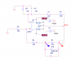
The gain is always 3. It takes a little time for the oscillations to build up to the clipping value, but it takes a gain of 3 or more to even get the oscillations started. The reason your circuit worked with R3 = 10k, R4= 15K and R6=5K is because the gain equation for your circuit is: 1 + (15K + 0/10K) = 2.5. that will stop the signal from growing. In that way, the tops of the signal aren't clipped by hitting the power rail.

in the above circuit, if the maximum gain that the resistor network can provide is only 3..how does startup for the oscillator occur? ive carefully read the post but im confused..sorry again
 
I said to set it wrong.
You must adjust the gain to be slightly more than 3 so oscillation can start and the output rises fairly quickly. Then let the diodes conduct a little at the peaks of the sine-wave which reduces the average gain to exactly 3.0 and holds the output at that level.
 
to try to understand it better, i did a simulation to compare nodes between X and Y (before and after the diode bridge) refer to attachment.
i noticed that throughout the transient wave, a constant voltage drop is always there (even at the peaks) meaning that the shunt resistance of the diode bridge never shorts..
if the diodes conduct at the peaks, shouldnt the resistor be shorted thus making no voltage drop between nodes X and Y at the peaks? if the diodes are conducting with some "internal" resistance, shouldnt there be at least a change in the voltage drop between nodes X and Y?
 

Attachments

  • 1.png
    1.png
    52.2 KB · Views: 251
  • 2.png
    2.png
    34.3 KB · Views: 244
or is it already from the beginning the voltage drop caused by the diode?

i did another simulation just for a voltage divider resistor network with the values in the previous attachment and noticed the voltage drop is aprrox 3.5V but the voltage drop in the previous simulation is approx 0.5 V

Could that be the reason?
 
You probably won't get much insight trying to measure across the diodes. They will conduct just enough to lower the gain, and only for a short time.
 
Diodes do not short in a circuit unless their current is extremely high.
In this oscillator the current in the diodes is very low so when the diode conducts it acts like a fairly high value resistor with a 0.6V voltage drop.
 
Last edited:
ic ic...i understand it now..
thank you both for your help=)

for the wien bridge frequency selective network, i input an AC sweep of frequencies in the lab to determine the phase shift response of the circuit. The cutoff frequency of my network based on the values used is approx. 470Hz

From the results, a nice graph was obtained from the frequencies 100Hz to 7kHz..

When the frequency got higher above this point, it seemed that the phase shifts that i obtained from the scope seem to be fluctuating up and down as opposed to readings that should keep decreasing to a negative maximum phase shift..(as opposed to the simulated graph)

Is there any reason for this? i did the measurements thrice to ensure that these fluctuations were not based on my error in reading the scope..
 
Status
Not open for further replies.

Latest threads

Back
Top