Electro Tech is an online community (with over 170,000 members) who enjoy talking about and building electronic circuits, projects and gadgets. To participate you need to register. Registration is free. Click here to register now.
Welcome to our site! Electro Tech is an online community (with over 170,000 members) who enjoy talking about and building electronic circuits, projects and gadgets. To participate you need to register. Registration is free. Click here to register now.
I am having trouble designing a Hartley oscillator using Mosfet's because Mosfet's a new to me still. All I know is that Q/I= switching time. I had to change the extension on the file, EOL won't take an sp3 file?
You have no gate bias control, it's connected to power??
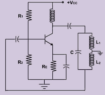
This is a Hartley oscillator in its commonest form; the only real change to substitute a a FET is to adjust the bias divider to give and appropriate standing current with the new device.
The coupling caps isolate the DC from the inductor and the DC levels & standing current are totally controllable:
Or with a choke in place of the resistor, as the output load:
Try moving the inductor coupling cap to the top end (or output) instead of the bottom end, then feed the bias at the inductor centre tap?
You should then hopefully be able to use a large decoupling cap on that to handle the AC ripple and much higher value divider resistors?
Why hartley? if you need high power, wouldn't a more conventional power oscillator with drive and feedback windings be more suitable, or a low power osc driving a power device?
You can expect most of power dissipated into the drain R on the left.
On the right there will be shoot-through current spike on each transition if the Threshold Vt is much lower than Vdd/2. So ideally Vt = Vdd/2, except for logic.
Vt or Vgs(th) @ I (<1 mA) may be tested as follows.
Do you plan to do everything with just a single transistor? It might be more efficient and generally better to use a small transistor for the oscillator and then a big transistor as a power stage.
Do you plan to do everything with just a single transistor? It might be more efficient and generally better to use a small transistor for the oscillator and then a big transistor as a power stage.
The value of the centre tap. cap. C2 is not critical as it is creating a shunt to ground, but just cannot be too much smaller than the main feedback resonant cap. But it is essential to have one to create the phase shift. C2 can be almost any value, say 100 pf to 100 nF but not 0 pF. fo=1/(2pi{(L1+L2)C}^.5)
The phase shift is 0 deg without the Cap. to ground.
This site uses cookies to help personalise content, tailor your experience and to keep you logged in if you register.
By continuing to use this site, you are consenting to our use of cookies.