Continue to Site

Welcome to our site!

Electro Tech is an online community (with over 170,000 members) who enjoy talking about and building electronic circuits, projects and gadgets. To participate you need to register. Registration is free. Click here to register now.

  • Welcome to our site! Electro Tech is an online community (with over 170,000 members) who enjoy talking about and building electronic circuits, projects and gadgets. To participate you need to register. Registration is free. Click here to register now.

Want to adapt PC headset to aviation radio

Status
Not open for further replies.

Allan Broadribb

New Member
I am a glider pilot and wish to adapt a PC headset to my Vertex handheld radio. I do not have engine noise in a glider and need to be able to hear the sounds around me so I do not need a heavy noise cancelling headset. Also, I am retired, enjoy projects and I'm cheap!

My handheld radio has an adapter for an aviation headset with the standard 0.25" and 0.21" female adapters. I have removed these and replaced them with female mini plugs for the PC headset. The result is the input to the earpieces is fine - I can hear loud and clear. However the microphone output is very low - it can be heard but it is very quiet.

So far I have learned that aviation headsets usually use 150 ohm amplified electret microphones that mimic the old carbon mics which are still the standard. So . . . it appears I need to make an amplifier for the microphone in the PC headset.

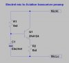
Audioguru posted a diagram for a powered preamp in the following thread which I think would probably work. However I would like a circuit that does not need an external battery. My handheld radio provides 5-6 volts to the microphone when the push to talk (PTT) button is activated which I assume is to power an amplified mic.

https://www.electro-tech-online.com/threads/need-help-for-electret-mic-preamp.33726/

I appreciate any help you can offer.

Regards, Allan.
 
Hi Allan,

do this little test: actually measure the open circuit voltage on the Mic pin with no Mic connected while the radio is keyed. Then, using your DMM in the mA DC mode, measure the current sourced by the Mic pin to ground with the radio keyed. This will let us calculate the value of the internal pullup resistor. (If you have a schematic of the radio, look it up).

What kind of microphone does your headset use? Dynamic? Electret?

With this info, I'll cobble up a no-battery preamp.

MikeMl, 3000+ hours in SELs

ps-If your headset has an electret element, the preamp will look something like this:
 

Attachments

  • Electret.jpg
    Electret.jpg
    34.5 KB · Views: 2,076
Last edited:
Thanks for your help - I hope this is all the info you need.

Open circuit voltage on the Mic pin = 6.0 - 6.5 volts
Current sourced by the Mic pin to ground = 2.1 mA
It is an electret microphone with 2.2k ohms impedance

I am looking for a radio schematic on the internet but have not yet found one.

Sincere thanks for your help.

Allan.
 
Allan,

Do you happen to know if the electret element inside your computer headset is the kind that has an integrated J-Fet amplifier? Using that type of electret, I am having difficulty getting enough gain powering it as well as the transistor amplifier off the Mic line out of the Yaesu simultaneously .
 
The packaging says it has an "amplified noise cancelling microphone element".

I can get a different PC headset or possibly change the mic. Allan.
 
The packaging says it has an "amplified noise cancelling microphone element".

I can get a different PC headset or possibly change the mic. Allan.

That's what I thought. Here is a preamp that uses a 3V coin cell. Good news is that current is drawn from the cell only when the Mic line on the Yaesu has >3V on it. I dont remember if you said that the 6Vo.c. is there while the radio is keyed, or simply when it is turned on. In either case, the current draw is ~500uA, so you shouldn't have to replace the cell very often. If you use a Double Pole PTT switch, you could break the MicHi wire and lower the battery consumption if that is an issue.

The breakthrough in thinking came when I realized I could use the presence of the mic bias voltage to turn on a battery switch, which powers the preamp only when it needs to be powered. A single npn transistor is ok for the preamp. The power switch uses a FET to achieve a high input impedance so it doesn't load the audio.

I tailored the freq response for voice frequencies only. I set the gain to produce ~350mVrms, which seems to be what aircraft mics do. There is not much distortion. Checkout the TurnOn/TurnOff transient. You shouldn't clip much of the voice message.:D
 

Attachments

  • Schematic.jpg
    Schematic.jpg
    111.7 KB · Views: 2,679
  • Waveform.jpg
    Waveform.jpg
    175.9 KB · Views: 712
  • Sweep.jpg
    Sweep.jpg
    232.9 KB · Views: 685
  • TurnOn_TurnOff.jpg
    TurnOn_TurnOff.jpg
    275.4 KB · Views: 692
I can't thank you enough and I hope that you have not created a monster which will come back to bite you many times in the form of dumb questions.

The 6 volts is there only when the radio is keyed - I assumed it is there to power the amplified mics regularly used in aviation headsets.

Here come the questions:

Does knowing the mic sensitivity is -39dB help?
What is "PP" on your schematic?
I can't find R7 on your schematic - is there supposed to be one?
Does R2 have to be close to the radio or can it be with the other components.

I assume the following:

1. The coin cell battery holder is indicating 2 x 1.5 battery cells.
2. The V2 at the switched bias source is indicating voltage.
3. U1 is the microphone.

Where would you recommend buying my supplies? I have used Mouser in the past but do not have any loyalty there.

My plan is to find a piece of circuit board, layout the components and join them with trails of solder. Then put the board in a small project box attached close to the radio with female mini jacks for microphone and PTT plugs.

What do you think - try not to laugh. Cheers, Allan.
 
I can't thank you enough...

The 6 volts is there only when the radio is keyed - I assumed it is there to power the amplified mics regularly used in aviation headsets.
Good, then the battery will last a very long time. Yes, most aircraft mics are either amplified dynamic or electret.
Does knowing the mic sensitivity is -39dB help?
That means your mic puts out 11mVrms. The one I modeled in LTSpice puts out 8mV.
What is "PP" on your schematic?
It is just a node label. In LTSpice, if you "name" a circuit node, then you wil see this name in the waveform plot. Note that I plotted V(DD) as one of the traces in the Turn ON/Turn Off plot to show when the preamp is powered.
I can't find R7 on your schematic - is there supposed to be one?
Nope, that is an artifact of LTSpice. If you add a resistor, and then delete it, LTSpice doesn't reorder the reference designators (unless explicitly told to do so).
Does R2 have to be close to the radio or can it be with the other components.
R2 is the Pull-Up inside the radio. I computed its value from your measurements, and included it only for simulation purposes. It is not part of the circuit you will build.

I assume the following:

1. The coin cell battery holder is indicating 2 x 1.5 battery cells.
2. The V2 at the switched bias source is indicating voltage.
3. U1 is the microphone.
Seems like I have some stuff around here that uses a single 3V coin cell CR2025 sticks in my mind, or maybe CR2035?
V2 is the bias source which exists inside your radio. I turn it on and off to simulate what happens when the radio is keyed.
Yes, U1 is the LTSpice model of an amplified electret mic. The SPL parameter adjusts its simulated sensitivity.

Where would you recommend buying my supplies? I have used Mouser in the past but do not have any loyalty there.

My plan is to find a piece of circuit board, layout the components and join them with trails of solder. Then put the board in a small project box attached close to the radio with female mini jacks for microphone and PTT plugs.

...

Mouser or Digikey works for me. For a one-of circuit, I use the double-sided Vector board that has plated-through holes on 0.1" centers, and a surround-ground-plane on one side. This works well by providing a good ground plane and allowing bypassing. **broken link removed**. You can saw it up with a hacksaw to get several projects on it...
 
Mike, here's my shopping list for Digikey. Would you be kind enough to check it and make sure everything is compatible. What is the best kind of battery holder - surface mount or will a through hole work on the prototype board?

R1 220k P220KCACT-ND
R3 270k P270KCACT-ND
R4 2.2k P2.20KCACT-ND
R5, R6, R8 100k P100KCACT-ND

C1 100n P5551-ND
C2 47n P5550-ND
C3 10n P818-ND

Q1 2N3906 2N3906FS-ND
Q2 2N3904 2N3904FS-ND

M2 BSS123 BSS123NCT-ND

Bat holder BU2032-SM-HD-9
Battery CR2025 P188-ND

Thanks, Allan.
 
I didn't lookup all the parts at Digikey. All resistors should be 1/4W axial-lead metal-film. I notice that the ones you selected have a min order of 10ea. Transistors, resistors, & Caps should have leads for thru-hole, as should the BU2032-1-HD-G-ND battery holder. The BSS123 is only available in SOT-23, so you will have to deal with that. Capacitor voltage rating ~10V is fine.
 
Supplies arrived this afternoon from Digikey.

I assume that transistors are symmetrical (there is no left or right side)

I assume with the prototype board I strip away the plated surface where it is not needed. Is there a particular way of doing this.

I am not sure of the wiring for the BSS123 - your schematic shows three lines into the left side and one to the right - the BSS123 has three terminals. Also the BSS 123 is miniscule can you recommend a way to connect it - my thoughts are to solder three wires to the terminals and connect these to the board.

Thanks, Allan.

"There is no such thing as a dumb question - but I'm working very hard at it!" AB
 
Supplies arrived this afternoon from Digikey.

I assume that transistors are symmetrical (there is no left or right side)
Go to Digi-key, put 2N3904 into the search bar. Follow it down to the specific part you ordered. There you will find a link to the PDF version of the maker's data sheet. Open the PDF and the pin order is shown. The one at right angles to the vertical bar is the Base(B). The arrow is the Emitter (E), and the other one is the Collector (C). Those are not symmetrical. Repeat for 2n3906 :rolleyes:

I assume with the prototype board I strip away the plated surface where it is not needed. Is there a particular way of doing this.

Post a picture or link to the specific one you bought.

I am not sure of the wiring for the BSS123 - your schematic shows three lines into the left side and one to the right - the BSS123 has three terminals. Also the BSS 123 is miniscule can you recommend a way to connect it - my thoughts are to solder three wires to the terminals and connect these to the board.
...

Fetch the datasheet for the BSS123. It shows the pinout. The way I drew it, the top pin is the Drain (D), the middle pin is the Gate (G), and the bottom pin (connected to MicLo) is the Source (S). These are normally mounted flat on a surface. Maybe it will straddle three isolated pads on your board.
 
Last edited:
No problem with the transistors - I'll check the data sheets.

The prototype board is:
**broken link removed**

For the BSS 123:
- the two pins on one side will line up with the prototype board and the other is between two holes. I'm concerned about the heat damaging it when I solder as it will be impossible to get a heat sink on it.

It appears to me from the schematic that:
- the drain is connected to the top pin.
- the source and the gate are both connected to mic lo.

OR - should the source be connected to mic lo and the gate connected to mic hi (via R1)

I'd like you to know that apart from trying your patience this is a fun project which I am enjoying. Allan.
 
No problem with the transistors - I'll check the data sheets.

The prototype board is:
**broken link removed**

I place the components on the non-ground plane side. I would connect MicLo to the ground plane. If you are careful, you can solder each resistor/transisitor lead into the plated-thru hole without bridging the gap to the surrounding ground. Those leads that are to be grounded to MicLo, just bend them over and solder to the ground plane.

For the BSS 123:
- the two pins on one side will line up with the prototype board and the other is between two holes. I'm concerned about the heat damaging it when I solder as it will be impossible to get a heat sink on it.

It appears to me from the schematic that:
- the drain is connected to the top pin.
- the source and the gate are both connected to mic lo.

OR - should the source be connected to mic lo and the gate connected to mic hi (via R1).

The Source of the BSS123 connects to MicLo, the Gate connects to MicHi through the 220K. The Drain connects to the 100K. I would tack solder some very small solid wire leads about 1" long to each pin of the BSS123 first (untwist some tinned stranded hookup wire to get a single tiny wire). Then grab that wire with needle-nose pliers while soldering it to the main board. That way, the heat shouldn't unsolder at the BSS123 end. Use hot glue to anchor the BSS123 as the last step.
 
Thanks - printing out and reading the data sheets for all of the components I see that a capacitor has an anode and a cathode - does this mean they too have to be installed in a certain direction?

Resistors too?

I have so much to learn.
 
Thanks - printing out and reading the data sheets for all of the components I see that a capacitor has an anode and a cathode - does this mean they too have to be installed in a certain direction?

Resistors too?

I have so much to learn.

Those capacitors (electrolytic, tantulum) that are marked with polarity symbols + - are polarized and must be installed with the + connected to the more positive voltage. There are a lot of capacitors (usually ≤ 1uF) that are not polarized, and it doesn't matter which way they are installed.

Resistors are not polarized.
 
Generally speaking, diodes and caps are polarized devices. Resistors and inductors are not. All diodes are polarized, some caps are not. NO resistors or inductors are polarized.
 
There is a delay in construction as I purchased the wrong capacitors - bought 47p instead of 47n, etc. With a little luck the new ones may turn up today - I hope so as it looks like another poor weekend for soaring - it has been very windy around here the last couple of weeks.

The CR2032 battery cells I ordered are supposed to have a life of 225mAh - with a current draw of 500uA does this mean the battery life would theoretically be 225/500 x 1000 = 450 hours.
 
The one nice thing about buying the wrong parts in electronics is there's always a use for something. Just put it in a box till you need it. And yes, if that's what the data sheet says, but it depends on what your actually current draw ends up being. 2032's have horrible internal resistance so the slower you discharge them the better.
 
Status
Not open for further replies.

Latest threads

New Articles From Microcontroller Tips

Back
Top