The capacitors arrived today and I finished the project. However it is not working for me. When I key the mic it emits a high pitched wine to the receiver I have in the garage and also through the headset. I removed the mic and headset keyed the mic and it still emits the same wine.
I have checked it over three times and can not find any soldering problems or accidental groundings. I checked all of the connections for continuity to ground and they all appear to be good.
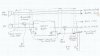
When I key the mic there is 6.15 +/- volts on mic hi and 3.0 volts on the output line to the mic.
By "output line to the mic" do you mean where C1, C3 and R4 come together?
Are you measuring the voltages with respect to "MicLo" (which is the same as the radio ground)?
If so, those sound correct.
While you are transmitting, what are you using as an antenna, or are you using a dummy load?
I suspect that RF from the antenna is getting into the circuit, is being rectified and is causing the audio feedback (the howl).
To prove the point, do you have a shielded 50Ω dummy load you could transmit into? Or perhaps an outside antenna?
I believe the battery switch is OK - when the mic is not keyed here is zero voltage on the emitter line from Q1 - when I key the mic there is 3.6+/- volts on the emitter line.
You mean the wire labeled PP in the schematic. That would be the collector of Q1 (it is drawn upside down).
If it is RF getting into it, you could try adding a 1 nF (1000pF or 0.001uF or "102") capacitor in parallel with R5 to bypass any stray RF to ground from the base of Q2.
When you built it, where is the circuitry box relative to the electret mic?
Is the mic in the headset and the circuitry in a small box close to the radio?
How long are the wires between electret and box?
Between the box and the transceiver?
Is the wire between the mic and the box shielded?
Is the wire between the box and the radio shielded?
Are these shields through connected to the radio ground (MicLo)?
Just to check;
C1=100nF or 0.1uF or "104"?
C2=47nF or 0.047uF or "473"?
C3=10nF or 10000pF or 0.01uF or "103", right?
Give me some feed back. Try the cap and I have some other ideas if you are still having problems.