Electro Tech is an online community (with over 170,000 members) who enjoy talking about and building electronic circuits, projects and gadgets. To participate you need to register. Registration is free. Click here to register now.
Welcome to our site! Electro Tech is an online community (with over 170,000 members) who enjoy talking about and building electronic circuits, projects and gadgets. To participate you need to register. Registration is free. Click here to register now.
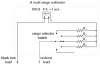
A voltmeter is simply a micro-ammeter with a resistor in series with it, likewise, for an ammeter, you put a low value resistor in parallel with a micro-ammeter.
A multimeter basically has both types, with the resistors switched.
Are you studying multimeter design or do you intend to build a multimeter to save money? If the former, I'd recommend requesting a multimeter manual from one or more of the major multimeter manufacturers, like Simpson, Triplett, etc., and studying it. You would probably find multimeter circuits in the series of circuit books by Rudolph Graf or John Markus. Additionally, long ago Howard Sams, publishers of books on electronics, put out a book on multimeter circuits and applications. Probably also had construction schematics.
Multimeters are quite simple in concept, but complex only due the the multitude of ranges and functions they include. So, once you understand how one range of a function works, you understand all the other ranges because the only difference is the resistor values selected by the range switch.
If the latter (want to construct one), unless you really want the exercise of building one, I would strongly recommend buying a multimeter. While it is conceptually very simple to put together a multimeter with very few ranges, once you try to include a practical number of ranges and functions, cramming all those resistors into a handy enclosure would be very demanding on your patience, skills. and manual dexterity and you will end up with a much less functional package than you can buy. Also, the special switching necessary to get all the ranges and functions in a single rotary switch would be virtually impossible to obtain.
With the modest cost of many hobby grade multimeters available today (at least in the U.S.), you would undoubtedly spend a lot more for all the resistors, switches, a sensitive meter, enclosure, etc.
I recommend saving your creative energies for a project that you can't buy dirt cheap on the market.
For one thing, to get reasonable sensitivity in a multimeter, you generally want a meter movement with not more than 50 microamps full scale sensitivity. It is unusual to find such a sensitive meter in surplus today. A lower sensitivity meter movement will result in a multimeter that might load down the circuit you want to measure.
Thank you for repling. I am doing an HNC college course, and the project that I have been set is to design (on paper - no building required) a multimeter for the blind. I know the idea of a blind man, or woman, using a multimeter is ridiculous and quite unsafe, but that is what I've been set.
I don't think that investing time in a design intended for someone who is blind would be wasted. I have several friends who are blind, totally or nearly so. I also have several friends who don't qualify as blind but they do have trouble veiwing things such as meters - particularly when lighting isn't so great.
In a number of ARRL Amateur Radio Handbooks they show an SWR meter that provides an audio output. The forward and reflected power outputs are connected to the convertor and the tones rise on voltage rise - fall on voltage drop. The goal is to get one high and one low.
What you might do is come up with something where a reference voltage can be programmed in - possibly via RS-323 or USB connection to a computer. Many people with vision difficulties have voice sythesizers that allow them to use their computers much the same as you and I. You might then use the audio tones comparatively - where the goal is to make adjustments to match the tones.
Friends with vision difficulties have commented that something like this would be great on the bench. The folks who are blind have others set things up for them - such as SWR meters or other monitoring instruments.
I like the idea of voltage to speech conversion, or possibly a braille display. Have you seen any circuits for such a thing. How would you go about making the speech system recognising what its input is and giving an output?
I have learnt a lot form this site http://www.faqs.org/docs/electric/DC/DC_8.html Would I be able to use the circuit shown below and connect it to a speech system.
Any clever ideas for making an output which a blind person could interpret would be most appreciated.
How about a large face analog meter movement with a window through which the user can feel the pointer position and braille numbers on the scale? Gently pressing the pointer down against the meter face could be fairly safe for the movement with a little practice. You would have to provide some type of dust cover to keep the movement clean.
How about a meter that announces the value in morse code. The numbers and the punctuation are much easier to learn than the letters.
Hook up a set of paddles and you could have configuration menus!
I like the idea of voltage to speech conversion, or possibly a braille display. Have you seen any circuits for such a thing. How would you go about making the speech system recognising what its input is and giving an output?
there are some voice programmable chips , in which u can record a voice say 0-9 , and use the bcd sequentialy as the address for the voice
eg: if the voltage is 12.99 -> voice "one two point nine nine "
I have found an IC which could convert a binary input into speech (by assigning each spoken number to a different address)https://www.electro-tech-online.com/custompdfs/2006/05/33193.pdf , but I need to convert the analogue reading into a binary number. My design currently works with a 1mA full scale deflection.
Please would you help me interface the analogue signal into speech.
u'll need an adc to convert the voltage to binary . i would prefer a micro with built in adc for the job , so that it can convert the read voltage values to bcd and generate address signals to the speech ic .
attach the image a gif image , it would be a lot smaller .
This site uses cookies to help personalise content, tailor your experience and to keep you logged in if you register.
By continuing to use this site, you are consenting to our use of cookies.