Continue to Site

Welcome to our site!

Electro Tech is an online community (with over 170,000 members) who enjoy talking about and building electronic circuits, projects and gadgets. To participate you need to register. Registration is free. Click here to register now.

  • Welcome to our site! Electro Tech is an online community (with over 170,000 members) who enjoy talking about and building electronic circuits, projects and gadgets. To participate you need to register. Registration is free. Click here to register now.

Digital voltmeter error

el34man

New Member
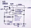
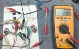
I have constructed a metering circuit (pic attached) using one-half of an LM358 as a DC x100 op-amp. The dc output (pin 1) connects directly to a 3-digit voltmeter (1/3rd inch self-type). The source of the voltage to be measured is the cathode of a power-pentode audio-output tube.

The cathode connects to chassis gnd via a 1 ohm resistor, so for example 40 milliamps of tube current produces 40 millivolts across the resistor, is amplified to 4.00 volts (.04 x 100=4.00V) by the Vc to be read as 40 milliamps on the display (the third digit and decimal point are hidden from view).

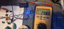
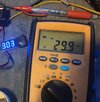
The circuit works well except the display is not very linear, tending to under-read at the low and high ends of the range. The intended range is 30mA to 99mA. In practice the readings are only accurate between 40mV and 70mV. Below this,
30mV displayed is more near 20mA and 80mV displayed is more like 95mA.

To ensure sufficient output swing I increased the IC vcc from +12v to +20V which improved the linearity,
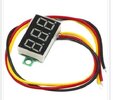
but only partially. The LM358 is capable of sinking output current but I'm wondering if the connected self-powered voltmeter is drawing too much current, as it has to light its 3 x 7-segment leds alone.

I am going to try splicing in the unused other half of the IC as a voltage follower, but would appreciate any comments as to what other issues may be affecting this design.

Note that the meter, being the type that obtains its operating voltage from the potential being measured. does not illuminate below 3.0V but that is not an issue in this case. The required range is 35 to 99 i.e. 3.5V to 9.9V true. (Sorry if this conversion from mV to volts and then red as mV is confusing, but remember only the first two digits are needed for display).

Many thanks in advance.

Gaz
 

Attachments

  • IMG_20230727_114738-01-01.jpeg
    IMG_20230727_114738-01-01.jpeg
    608.3 KB · Views: 186
Power opamp then, some down to 1 mV offset, and capable 350 mA :


100 mA :


Of course specs have to be evaluated, like output swing for the given display LED current, max allowed
supply V,.....


Regards, Dana.
 
Last edited:
Thanks on all contributions so far. I will restate some factors here just to throw a bit more light on it.

1. I am employing a tiny 3-digit 7-sement display unit. I am assured of its linearity and good accuracy on outboard tests. With the unit now removed I am still measuring the under-reading problem as reported on the 358's output pin (1).

2. This display module does not function below 3v0 input. This does not matter as =<3v in is a bonus as the measured device shouldn't be operating that low in service!

3. The original design was operated at 12V rail but the under-reading was worse. Elevation to 20V lessened the error to what it is now.

4. Due to wiring limitations a dual-rail op-amp isn't a consideration. Input offset isn't important as a display error of +/-5% is acceptable.

5. The digital meter cannot be included in any feedback design due to its high input resistance. Probably inserting a 100 ohm resistor in the feedback loop and placing the dig. v/meter across that may work better?

6. Please guys, I am not familiar with DC gain being expressed in dB units. Decibels belong to AC gain. A gain of x100 should simply result in proportional output i.e. 40mV in gives 4 volts out, 90mV gives 9 volts out.

7. The source of my measurement is across a 1ohm cathode resistor in a valve audio output stage. 10mA of current through the valve results in 10mV being developed across the series cathode resistor (E=IxR). The range of current to be monitored is 35mV to 99mV (35mA to 99 mA).

I haven't yet got back to fiddling but I'm hoping tomorrow. Stick with me guys, we must crack this (don't want to use an analogue meter if can be helped due to size limitation).

Cheers. Gary
 

Attachments

  • Screenshot_2023-07-31-19-28-52-319_com.google.android.googlequicksearchbox-01.jpeg
    Screenshot_2023-07-31-19-28-52-319_com.google.android.googlequicksearchbox-01.jpeg
    41.5 KB · Views: 86
Thanks on all contributions so far. I will restate some factors here just to throw a bit more light on it.

1. I am employing a tiny 3-digit 7-sement display unit. I am assured of its linearity and good accuracy on outboard tests. With the unit now removed I am still measuring the under-reading problem as reported on the 358's output pin (1).

2. This display module does not function below 3v0 input. This does not matter as =<3v in is a bonus as the measured device shouldn't be operating that low in service!

3. The original design was operated at 12V rail but the under-reading was worse. Elevation to 20V lessened the error to what it is now.

4. Due to wiring limitations a dual-rail op-amp isn't a consideration. Input offset isn't important as a display error of +/-5% is acceptable.

5. The digital meter cannot be included in any feedback design due to its high input resistance. Probably inserting a 100 ohm resistor in the feedback loop and placing the dig. v/meter across that may work better?

6. Please guys, I am not familiar with DC gain being expressed in dB units. Decibels belong to AC gain. A gain of x100 should simply result in proportional output i.e. 40mV in gives 4 volts out, 90mV gives 9 volts out.

7. The source of my measurement is across a 1ohm cathode resistor in a valve audio output stage. 10mA of current through the valve results in 10mV being developed across the series cathode resistor (E=IxR). The range of current to be monitored is 35mV to 99mV (35mA to 99 mA).

I haven't yet got back to fiddling but I'm hoping tomorrow. Stick with me guys, we must crack this (don't want to use an analogue meter if can be helped due to size limitation).

Cheers. Gary

As I pointed out back in post #8, you're using a completely incorrect unit - it's NOT a voltmeter, it's a battery test meter, which is why it's powered from the input.

You need to dump the battery tester, and get a proper voltmeter, which will have a separate power feed.

Unless you can separate the connections on the existing battery tester?.
 
Glad to hear/see power for the digital meter supplied in a separate connection
than its input. No need for power OpAmp.

As stated earlier the offset input referred V of an LM358 is, worst case,,
is - 9 to +9 mV, so meter would be off -.9 to + .9 volts of ideal, worst
case. You have added a offset control trimpot, and adjusted that out ?
Or used a OpAmp with a Voff << 1 mV......?

Your cathode R pickup point, is AC bypassed with large cap ? No AC
present as your module is DC only ? If, with a scope, you see AC on
cathode, because meter has High Z in, just use a lowpass filter, say
100 K ohm from cathode and a 1 uF to ground to get rid of it at
input to 3 digit meter.

1690798327030.png

1) The cathode pickup point, have you used a scope to look at its DC quiescent bias
level ?

2) What is the error spec and model # of the DMM used to measure V's,
3) same for 3 digit module meter ? 4) Is this it for module ? :


5) I think there is confusion, these modules used to be offered with differential
inputs, not just a single level input. So black wire is ground, Red is supply for
module, and yellow for input ? So power is NOT being sourced from same
input used to measure ? Now module may also spec that it can be used where
power is tied to input, such that it measures system power supply V, is that
what you are doing ? If thats the case, and module takes 20 mA to operate, the
LM358 may not be able to supply that. it has a 20 mA worst case source, which
would make design marginal in supplying module and doing the measurement.
Hence power opamp would be needed in this mode of supply and V cathode
on same pin.

So questions 1) thru 5), 5) multiple questions


Regards, Dana.
 
Last edited:
UPDATE. Hi Dana, Nigel and all others who contributed logical comments.

The problem unit is assembled on a tiny pcb located a few inches from the display. I decided to build a separate bird's-nest version on the bench, instead of poking in and around the high voltages associated with valves which are nearby the problematic item.

I configured a variable current source and got to examining the duplicate circuit and found this one worked exactly as intended. Yaye! I cannot explain atvthis point what is wrong with the problem unit but here are the results from the test version.

1. This time I used a larger 4-segment display of the same 3-wire type. I tested in both configurations i.e. separately powered and powered from 358 output. There was no significant difference between connection modes, the voltmeter tracking accurately with typically a displayed 1% error (see photos attached). The quoted spec is 3%.

2. The current measured inputting to the meter is steady at 7mA, regardless of 2 or 3-wire mode. It must be appreciated that these are smart modules, incorporating their own negative-rail split-supply circuitry, allowing unbalaced supply connection despite common earth.

It was found that this display module will function with inputs down to less than 2V, which is 20mA at my cathode measuring point - far less than I need!

3. I tested at varying supply voltage to the 358. Of course the measuring range improved at a higher Vcc. A 12V rail allowed output to 9.5V (cathode = 95mA) while 18V displayed a maximum of 12.2V (= to 122mA at cathode).

4. Input offset error is indeed .9mV, reflected as an .9v overread. At times this dropped to .1mV. It is an acceptable condition however as extreme accuracy is not required, being a guide or trend indication only.

5. I tried 12K resistor to gnd across 358 Pin 1 with no discernible result. Its series current measured 8mA. Will leave it out.

6. Dana, I appreciate your a.c. component comment and it is applicable. But in my case, this is a no-signal measurement, with program audio being muted. In a class AB valve push-pull amp, cahthode current is measured in a steady-state ("idling") condition, so no such ac corruption is present.

I will report back again when I have determined what is exactly wrong with the original setup.
 
Here's the readings on bread-board test, my yellow meter is reading the INPUT mlivokts the ue display is the 4-digit display with the 4th digit covered up. In practice only the first two digits will be read. Note that I used 1K via the 100 ohm preset to calibrate. The final value is equivalent to 1080 ohms, the extra 80 provide downward offset correction. I will go with 18V op rail, 1k + 100E trimmer or 1K + 82E fixed and 12 (or 20V) to display module.
 

Attachments

  • IMG_20230802_173009.jpg
    IMG_20230802_173009.jpg
    3 MB · Views: 105
  • IMG_20230802_173009-01.jpeg
    IMG_20230802_173009-01.jpeg
    991.5 KB · Views: 107
  • IMG_20230802_200747-01.jpeg
    IMG_20230802_200747-01.jpeg
    1.1 MB · Views: 101
  • IMG_20230802_172536-01.jpeg
    IMG_20230802_172536-01.jpeg
    1,017.1 KB · Views: 104
  • IMG_20230802_173916-01.jpeg
    IMG_20230802_173916-01.jpeg
    788.3 KB · Views: 100

Latest threads

New Articles From Microcontroller Tips

Back
Top