Continue to Site

Welcome to our site!

Electro Tech is an online community (with over 170,000 members) who enjoy talking about and building electronic circuits, projects and gadgets. To participate you need to register. Registration is free. Click here to register now.

  • Welcome to our site! Electro Tech is an online community (with over 170,000 members) who enjoy talking about and building electronic circuits, projects and gadgets. To participate you need to register. Registration is free. Click here to register now.

ICL7107 Voltmeter calibration

Status
Not open for further replies.

123mmm

Member
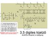
Hi, I need some advice regarding the attached schematic. I built the schematic, it is working but I don't know how to calibrate it. I need to measure between 0 V and 50 V.
I set the Rx1= 100R and Rx2a= 100k, but if I rotate R4, then the displayed value modifies.
Do I need to calibrate it using a standard voltmeter ?
 

Attachments

  • voltmeter_schematic_7107.JPG
    voltmeter_schematic_7107.JPG
    136.6 KB · Views: 312
Your options are as follows. Calibrate the 200 mV range and let the resistors to their thing. e.g 1%, 0.1% etc,

or calibrate near the nominal voltage you need to measure accurately. e.g. inject 25V and calibrate to 25V.

A calibration source is usually better than your meter. It might be a 2.500 V source.
 
The calibration should be as follows.
1. Set the values for Rx1 and Rx2a
2. Set the displayed value by rotating R4 ?
 
Hello shokjok , the text is this:
FIGYELEM!! A 2000V csak egy elméleti határ.
Eszébe se jusson senkinek kipróbálni!
Using google translate:
 

Attachments

  • translate.JPG
    translate.JPG
    37.3 KB · Views: 165
Status
Not open for further replies.

Latest threads

New Articles From Microcontroller Tips

Back
Top