Continue to Site

Welcome to our site!

Electro Tech is an online community (with over 170,000 members) who enjoy talking about and building electronic circuits, projects and gadgets. To participate you need to register. Registration is free. Click here to register now.

  • Welcome to our site! Electro Tech is an online community (with over 170,000 members) who enjoy talking about and building electronic circuits, projects and gadgets. To participate you need to register. Registration is free. Click here to register now.

Voltage Problem...Need Help

Status
Not open for further replies.

Inferno

New Member
hello there...
i m trying to finish this project out..it s about a walking robot..i would post everything about it when it s done and when it works.. but for the moment i need your help please....
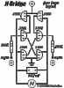
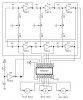
well the problem is that as you see in the attached circuit... the voltage used is 5 Volts...the voltage suitable for logical signals...so i think that at the motors output the voltage will be 5 Volts also.. the problem is that i need to use powerfull motors and the 5 Volts output is not that good ... i need a 12 Volts output... so.. what can i do ???
can i use 12 volts to feed the 74hc245 ???( it may be a stupid question for you guys...but i m sorry i don t have lot of knowledge in these things) if not ...can i put regulators at the output to tansform the 5 volts tension to 12 volts ?? will that harm the circuit???
plz help..
 

Attachments

  • 3-schem.jpg
    3-schem.jpg
    39.9 KB · Views: 216
Yup you are right. For higher power motors, it's better to use higher voltage motors (if you even have a choice between low and higher voltage). This lets you get the same amount of power with less current so you have less losses.

You want to take your 5v logical signal to control a larger switch that will allow current to flow to your motor. You need to do this whether or not you are using a 5V motor or a 48V motor. You cannot hook up your microcontroller pin to the motor even if it is a 5V motor since the uC cannot drive that much current through its pins. You 74 IC will not work because you are still in the mindset of connecting a uC pin straight to a motor. Its the same as the uC- it can drive enough current through its pins.

If you only have a 5V battery or somrthing close to that, it's too much work to make (or probably buy components/circuits- very expensive) that step up voltage at current levels motors use. Your best bet is to use more batteries and step down the voltage going to your logic with a regulator (less current and power invovled), rather than stepping up your logic voltage supply for a motor. Or better yet, just get a motor that uses voltage around your battery voltage. You do NOT want to regulate the voltage going to the motors (you can but it takes high power regulators and if they are linear regulators you have horrible efficiency. If they are not linear, then they are very complex and expensive because motors need so much current. So you want the motor (and power connections of the h-bridge to draw current straight to the batteries BEFORE the regulator for your electronics.

You need an h-bridge. (brushed motort i assume):
https://www.modularcircuits.com/h-bridge_secrets1.htm

If you are using RC servos ("elbow motors" rather than normal wheel motors)then all of that circuitry is inside the servo already.

If you do increase the voltage of the motors, make sure the motord can handle it. What motors are you using?

I hope this has given you enough information to ask specific qurstions which are much easier to answer for us (especially me- sprained wrist.) and easier for you to understand.
 
Last edited:
the motors i want to use are 12 volts dc motors....i ll use a regulator to provide the 5 volts needed for the IC .....but what about the output going to the motors ??? what will i have to do ?? sorry but i didn t understand all of the things you said... i appreciate your help :)
another question plz.... do i have to connect the VCC and Ground pins in the 74hc14 IC ??? in the circuit they don t show them and don t talk about connecting them ...
 
ok... i made some researches and figured out what i was missing.. thanks a lot for putting me in the right way .... i know now exactly what i have to do .... the problem is that i was searching google for a suitable H-Bridge... but couldn t find a one ... i need it to be operated by 5 volts and can drive a 12 volts motor... it s not a big current... i m sure that 3 amps is more then enough....so.. do anyone have a name for that ???:D
anyway i m thining also of building my own h-bridge with mosfets and diodes....but this will be a big cicuit...i have 3 motors.. this means 12 mosfets...anyway...if you can help me with a name this would be gr8 !!!
and 10x again DKNGUYEN for your precious help
 
A motor driver does not have to have the same logic voltage as motor voltage. Logic voltage is dictated by what voltage will turn on the transistors (or in some cases what voltage will activate the gate drivers which are used to supply more current and voltage to the gate of the transistor to drive it quickly and effectively). The motor voltage it can handle is dictated by the votlage the transistors can withstand across drain and source.

I dont know of any name...you could build your own (you might need to have gate drivers which can make things a whole lot more complicated if you want to use NMOS transistors on the high-side). If you choose transistors that require 10V or 15V at the gate to turn on completely you also need gate drivers. THis will probably not be the case since your motor driver is small.

For diodes, you need to use schottky diodes or some other fast switching diode to be able to protect the transistors from the motor's inductive flyback when switching.

You sound like you prefer to just buy one:
https://www.pololu.com/products/pololu/0120/
https://www.pololu.com/products/pololu/0410/

Make sure to look at the voltage and current ratings since the cheapest one can only handle up to 9V and 1A per motor which may be enough for you (I don't know). They're a bit cheaper than the other ones. Also notice the giant IC they use on the larger motor driver...you might be interested in it. It's the only motor IC I'd consider using. I personally prefer to build motor drivers from scratch or buy a complete one- I don't like using H-bridge ICs, so I didn't post any except that one.

BTW, most complete motor drivers (and H-bridge ICs) can be activated by 5V logic. Pay more attention to the maximum motor voltage they can handle, and they *might* need a third voltage supply to switch the transistor gates inside the IC.
 
Last edited:
lOOK AT A ULN2803 OR ULN2804

THE ULN2803 IS TO INTERFACE ttl TO OUTSIDE WORLD
THE ULN2804 IS FOR INTERFACING CMOS TO OUTSIDE WORLD
oups the caps lock was no sorry
this chip is used for motor control. type in on a search engine and it will show examples of using.
remember the outputs are inverted.
hope this helps??
 
first 10x MrDeb for your help but i don t think i ll use the ULN ic s ....coz i couldn t find them here...
back to your post DKNGUYEN... i m thinking of using 12 mosfets with 12 Schottky diodes....in a very standard usual h-bridge connection.....
i ll get mosfets ordered by a 5 volts at the gate and able to handle a 12 volts 3 amp at the drain and source...i think this will not be so hard to do .. and i thin that this would work... i need your opinion to be sure about it ....i mean the output from the 74hc245 is about 5 volts...it can run the gate in the mosfets.....am i right ???? and by the way ... the switching between the two directions is made every 1 or 2 seconds...and the whole project is not that professional.. i just want to let that stupid doctor see it running and this will do the job for me ... hehehe....
 
Mouser electronics has lots of the uln2803 and 2804s
might be easier if your only running 12v
 
by the time you purchase everything and put the time into building and troubleshooting your own electronics, it would probably just be easier and cheeper to buy it already made. However, I understand wanting to learn fromt the project, as I am doing something similar, and like to do everything by hand so that I get the full experiance and knowlege. Let us know how your progress goes. Oh, and dont forget that any mosfet disipating more than one amp needs to be heatsinked in some way shape or form, and also, if you are not familiar with them, they are VERY sensitive to ESD, electrostatic discharge, 100 volts can destroy them, this is less voltage than is even able to be felt by a human at such low amprage, so leave them in the protective foam until you use them, and make shure you are properly grounded before you begin.
 
i ll use the IRFU3708... it s perfect with the logical voltage... it s 100% opened when the gate voltage is 5 volts...and it can handle up to 60 amp !!
 
Some Real Help !!!!!!!!!!!!

guys i really need a big help here... there s something i dont understand....
in the above circuit.... on the motors output i can measure from -5 to +5 volts...and this is the normal thing and the target from this circuit...to oscillate the tension on the motor so he can make alternative loops....when i measure any output with the ground...the tension varies from 0 to 5 volts...when i measure an output with an other the tension varies from -5 to + 5....anyway... the problem is that i want to drive 12 volts motors....i builded an H-Bridge.. but it didnt work !!!!! what the problem is????? is it that mosfets don t deal with fastly changing pulses ???? and an other question... is a mosfet normally opened ?????? i really appreciate your help ... i want to know if the use of an H-bridge is right here.... and if no... what solutions do i have ?????
I used irfz44n mosfets....maybe they are not good for this task ???? i used also with them schotsky diodes...
so anyone could figure out a solution ???
 
Last edited:
You can use H-Bridge circuit to drive DC-motor to move forward and backward only. If you need to control it's speed, try it with PWM.
If your H-Bridge get fail to work, you should check out the mosfets Vgs.
 
hello guys....
i dunno what s happening here..but i can t find a good solution for my 12 volts motor....i tried many h-bridges and they are not working ... it looks like the 74HC245 can not supply enough tension or current to drive the mosfets.....anyway....since the motors i m using need just 0.1 amp by motor.. i m was thinking ... maybe i can use 4 transistors to make a such h-bridge ???? plz guys.. i need help in this...what transistors to use???? how to connect them ... ?? i repeat that the motors are 12 volts... 0.1 amps... and the control tension is 5 volts(out from the 74HC245)
 
An h-bridge that uses 4 N-channel Mosfets has low side Mosfets with their source grounded and their gate is 5V when the Mosfet is turned on and the gate is 0V when the Mosfet is turned off.

The high-side Mosfets have the drain at +12V, the source to the motor and the gate must be +17V for the Mosfet to be turned on and must be 0V for the Mosfet to be turned off. A Mosfet driver IC has a voltage stepup circuit to drive the high side Mosfets.
 
first Nigel it s a very little kind of beam 4 legs walking robot...
and audioguru...i can t use mosfets... i don t have a 17 volts source in the circuit.. and i can t add any other components to the circuit....i didn t find any mosfet that is turned on with 5 volts on the gate...
i think that a h-bridge made with transistors would be enough here...since the motors don t need high current...i just wanna know what transistors to use ???
 
THe motor actuall uses 100mA, but is designed to be run at 12V? that is a bit odd. WHy isn't it rated for 5V or something like that?
 
hehehhe... guys... i ask you for help and you ask about things that i dont know and don t care about :p
i have no idea why this motor is like that ....and i don t care.. this is the motor i m using... can t you just accept that a such motor exists ??
i really appreciate your help ...but what you do is just making things more confusing for me ...
anyway... 10x for your help
i ll try the h-bridge posted here :
http://www.geocities.com/beamnet/H-bridge.htm
hope it works ... if you have anyother ideas.. let me know ... and 10x
 
Status
Not open for further replies.

Latest threads

New Articles From Microcontroller Tips

Back
Top