Continue to Site

Welcome to our site!

Electro Tech is an online community (with over 170,000 members) who enjoy talking about and building electronic circuits, projects and gadgets. To participate you need to register. Registration is free. Click here to register now.

  • Welcome to our site! Electro Tech is an online community (with over 170,000 members) who enjoy talking about and building electronic circuits, projects and gadgets. To participate you need to register. Registration is free. Click here to register now.

Voltage limiter, big voltage input intervall

Status
Not open for further replies.

hantto

Member
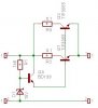
I'm trying to build a voltage limiter for a moped. I tried using zener diodes, but the ting got so hot that the solder on it's joints metled. Then a switching regulator came to mind. Won't these accept a long input voltage range and output the specified value? The voltage range is from 18Vac to about 40Vac, I want a output value of aprox 12V ac or dc. The current requrement is about 3A. So will a LM2576 be suitable for this cind of application? Can I connect them in paralell to obtain a higher current value?

Maybe there is a simpler and cheaper method of doing this. Please tell me if you do know a better way. :)

Thanks for your time!
 
Russlk said:
Where are you getting this 18 to 40 VAC from?

From the magneto (the generator on the moped).

Russlk said:
Why do you want to reduce it to 12 volts?

Because otherwise the headlights (and other electronic stuff) will burn at high rpm.

Russlk said:
Why would you convert it to DC?

I don't need to. I just said that it does not matter if it is AC or DC.
 
The output voltage from the generator will have much ripple. Any ideas? I don't need to regulate the voltage just limit it.
 
hantto said:
The output voltage from the generator will have much ripple. Any ideas? I don't need to regulate the voltage just limit it.

As an ex-biker, I've had a couple of bikes (trail bikes) where the lights worked directly off the engine - on both (and on all similar systems I've seen) there's no regulator at all, the system is self regulating under the load of the headlight bulb. Usually the side light, brake light, and indicators work off the battery, so they still work when you slow down - but the headlight is connected straight across the output of the alternator, which results in the light almost going out when you stop.

There should be no need to change anything from how it was designed, have you altered it in any way?.
 
No i haven't altered it in any way, yet. It currently has a 6v limiter. The reason why i want more voltage is that I need brighter headligts. The lamp fitted there now is poor. There are other reasons aswell, all the modern equipment is 12v so it's gettign more and more difficult to find 6v stuff. I'm also going to design my own PIC based controllsystem for various accessories, leds and other things. I also think that it is a waste to throw so much energy down the drain all the time. With a 12v system I could also fit an ass-warmer :) so it would be warmer to drive during the winter.

Would it be possible to use a swiching regulator as stated above?

Thanks for your response, sorry for the delay.
 
Well hantto if Your going to use a pic MC or anything that is IC based you do indeed have to worry about ripple.

The easiest solution is to use an LM 317 . It's a 3 pin regulator that requires nothing more then a heat sink ( the bikes frame ) and a variable resistor. You will need a ~35V or so zenier and a 1 watt 100 Ohm at the input and filtering at the output . No biggie just a coupla caps , say 1 100uF @ 30v or so and a .01 mF for noise.

The headlight is a bit more involved. They draw many amps. an LM 723 driving a sinked tip 120 ( you may need to go higher in A ratings depending on the draw of the light ) or eq should do.
 
hantto said:
No i haven't altered it in any way, yet. It currently has a 6v limiter. The reason why i want more voltage is that I need brighter headligts. The lamp fitted there now is poor. There are other reasons aswell, all the modern equipment is 12v so it's gettign more and more difficult to find 6v stuff. I'm also going to design my own PIC based controllsystem for various accessories, leds and other things. I also think that it is a waste to throw so much energy down the drain all the time. With a 12v system I could also fit an ass-warmer :) so it would be warmer to drive during the winter.

Your alternator can only supply a certain amount of power, and it's voltage output is limited by the number of turns in the alternator. An alternator designed for a 6V system isn't going to provide enough output for a 12V system unless you rewind it with thinner wire and twice as many turns. The existing regulator won't be throwing too much away, and then only at high engine revs.

I toyed with trying to convert my Yamaha DT400 years ago, but chickened out of rewinding it :lol:
 
TillEulenspiegel, I know very well that I have to worry about the riple, and i'm well aware of the 3pin regulators. I first want to get the voltage limited to 12v so i can regulate it down so suitable levels for ic's.
Thanks for the suggestions anyway, i'll look into that ic.

And about the outputlevels of the generator, it is 14VAC on the lowest rpm, that's more than enough (and yes I had a load on it (a h4 bulb)). Many other people have also done this with exelent results. So it is very possible to make it a 12V system without rewinding the coils. :)
 
hantto said:
And about the outputlevels of the generator, it is 14VAC on the lowest rpm, that's more than enough (and yes I had a load on it (a h4 bulb)). Many other people have also done this with exelent results. So it is very possible to make it a 12V system without rewinding the coils. :)

Good - that sounds hopeful!.

Have you tried contacting the other people who have done it?, and see what they did!.
 
Some have not done anything but taken the regulator away, but the suffer from frequent bulb burnouts. Others have stolen a regulator from another 12v vechile like a snow-scooter, some have bought new regulators, but they are expensive. So I will not buy a readymade one.

I could allways use a 3pinregulator with some extra pass-transistors (hot hot hot!)
 
hantto said:
Some have not done anything but taken the regulator away, but the suffer from frequent bulb burnouts. Others have stolen a regulator from another 12v vechile like a snow-scooter, some have bought new regulators, but they are expensive. So I will not buy a readymade one.

I could allways use a 3pinregulator with some extra pass-transistors (hot hot hot!)

The only system I've ever seen for this was on some old Triumph's, they used to have a large zener diode mounted on a hetsink between the front forks (nicely in the air flow). The zener was just connected directly across the battery, and if the voltage tried to rise too high bypassed the extra current through the zener.

You could do something similar with a smaller zener diode feeding the base of a power transistor - but as you say, things are likely to get hot!.
 
I designed a circuit. I could allways lead the excess warmth to my ass :)

Errors? other mistakes? I'm not sure about the 1k5 resistor, will it drop the voltage to much under load? should i add one more buffer stage?
 

Attachments

  • limit.jpg
    limit.jpg
    11.8 KB · Views: 653
hantto said:
I designed a circuit. I could allways lead the excess warmth to my ass :)

Errors? other mistakes? I'm not sure about the 1k5 resistor, will it drop the voltage to much under load? should i add one more buffer stage?

It's a simple series regulator, your only mistake is the two 0.1 ohm resistors, they should be in the emitters of the two power transistors.

However, it has the disadvantage that it will always waste some power, the Triumph zener diode circuit I mentioned previously was a parallel regulator, and didn't waste any power until it had to.
 
Status
Not open for further replies.

Latest threads

New Articles From Microcontroller Tips

Back
Top