Hello,
I have run into another problem, (two actually)
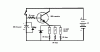
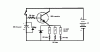
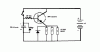
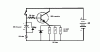
The first one is that the three relays I am trying to activate at the same time are turning off one by one instead of all at the same time. They go off one by one with the time interval of less then a second between each one going off.
Is there a way to fix this?

also... the relays do not activate when I use my "almost dead" battery its voltage is 7.81 V.
Audioguru said that is should work up to 6.35V
if anyone can help please do
thanks,
Geroge