Continue to Site

Welcome to our site!

Electro Tech is an online community (with over 170,000 members) who enjoy talking about and building electronic circuits, projects and gadgets. To participate you need to register. Registration is free. Click here to register now.

  • Welcome to our site! Electro Tech is an online community (with over 170,000 members) who enjoy talking about and building electronic circuits, projects and gadgets. To participate you need to register. Registration is free. Click here to register now.

voltage drop

Status
Not open for further replies.
audioguru said:
I agree with Nigel.

I see what you mean, the relay could be simply operated by the switch directly. My point was that if you want to do it this way (for whatever reason), the second resistor is not necessary as you also pointed out.

Len
 
ok........

Audioguru,

my school has no electronics classes, only engineering classes that don't help for electronics stuff....

the only help I have gotten was from a teacher that was a former mechanical engineer, he keeps misleading me so that is why I came to this web site. This project is not a school project.

I have some things backwards in the circuit as you mentioned; my knowledge is VERY basic, so I am requesting help.

I keep posting in a Microsoft word document because the forum won’t accept the version of Paint I have (or something like that). Sorry for the inconvenience.

Are the components just backwards, or is the entire circuit just messed up?

Please help,

George
 
Hi George,
I am glad that you are learning electronics without even having it in school. Perhaps you should first learn "Ohm's Law". It defines the relationships between voltage, current and resistance. Then you can learn the difference between an NPN and a PNP transistor. It will show you which polarity a battery or power supply should be connected to them.

I make all my schematics and modifications to other posted schematics with MS Paint. It sketches straight lines with the Shift key down and moves things around just fine. You can "save as" a GIF that you can post here.

In your last posted circuit the capacitor, diode and battery are sketched with the wrong polarity. Actually the battery symbol is correct, with the long bar as the + terminal, but its + and - markings are on the wrong ends.

Since each relay needs 180 ohms in series, and you have 3 relays, you can parallel the relays and use a 62 ohm resistor in series with the combination instead of 3 separate 180 ohm resistors. 180/3 = 60 but 62 ohms is the nearest standard value. :lol:
 
I am certain that audioguru meant nothing he said to be condescending, only pointing out that he noticed that you have yet to have very much working knowledge in electronics and, as such, we may need to explain things more fully.

By the way, if you are running Windows 2000, XP, or Server 2003, you can download **broken link removed** which is a vastly updated version of Windows paint that was done as a collaboration between Washington State University and Microsoft. It is a small download and you'll be able to save your files in any format supported by this forum plus many more.
 
Hi TekNoir,
I find that if I save a sketch in Paint as a certain file type, then the pic has a pattern of many dots in its background. So I save it in Paint as its default, a huge bitmap, then open it in my ACDSee viewer and save as a GIF.
 
My laptop is issued by my school and we can't download most things...so i have to keep posting in Microsoft documents, sorry

Audioguru,

could you please help me with correcting my circuit, the diode is an easy fix, but what about the battery and capacitor.

also, does it matter which way the emitter and collecter pins of the transistor are facing, it seems to work both ways in my circuit

thanks,

George
 
Why do you need 10 relays? Are you aware that you can buy relays with more than one contact set?

I suggest you post that part of the circuit so we can see what you are doing.

I draw circuits in PowerPoint and, when ready for posting, do a "save as" a .gif or a .png. Both can be downloaded into this forum and are visible. Like the ones posted by Miles Prower and Audioguru

Len
 
Hi George,
Try making a schematic with MS Paint and save it as a GIF file type that can be posted here and it shows on our screens.

Swap the battery's "+" and "-" symbols so that the "+" is at the top.
Turn around the capacitor so that its "+" end is also at its top.

The emitter and collector pins are very important to a transistor circuit. You can damage a transistor with them reversed. You should always have a datasheet for transistors and IC's which are available with a quick search on www.google.com. I copied a datasheet from there into MS Paint, cropped it and bordered it, saved it as a GIF and here it is:
 

Attachments

  • 2n3906.gif
    2n3906.gif
    5.3 KB · Views: 550
thanks Audioguru,

I need a NPN transistor with the changed circuit right?

I finally posted it correctly

it it finally ok now?

thank you,

George L.
 

Attachments

  • revised_circuit_10101.gif
    revised_circuit_10101.gif
    13.6 KB · Views: 520
ohhh...i forgot to metion one thing :oops:

the relays i am using at DPDT, they don't come with anymore contacts then that right?

The max i am using is actually four.

George L. :wink:
 
Hi George,
Your circuit is posted as a nice GIF and is perfect :lol: with the 2N3906 PNP transistor. Don't turn down the pot too low or it will burnout and kill the battery when you close the switch. Also don't use more than 10 relays and their 180 ohm voltage-reducing resistors. :lol: :lol:

You can get relays with many more contacts but they draw too much current. What are you going to drive with the relays? Usually we use transistors, Mosfets or triacs to drive loads and they don't use the high operating current and last much longer than relays.
 
Thank you audioguru,

i am planning to run 2 motors and maybe a few LEDs (for looks) :wink: of the same battery powering the relays. Is there a way to determine how long the battery will last, and also, just curious, how did you come up with 180 ohms for my circuit(V=IR)?

thanks,

George
 
Hi George,
Motors that do any work have a high supply current and would kill a little 9V battery quickly. The relay and its wasted power could be replaced by transistors to drive the motors and LEDs without much waste. Electric wheelchars and golfcarts don't use relays, they use transistors to drive their motors.

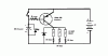
I calculated the 180 ohm voltage-reducing resistors like this:
1) You said the relays are 5V ones but didn't tell us their coil resistance.
2) You measured 37mA when the circuit was without a voltage-reducing resistor for the relay, and a 9V supply.
3) The 10k resistor uses about 1mA from the 37mA total and the transistor's 10k base resistor uses another 1mA leaving 35mA going through the relay's coil.
4) 9V/35mA is 257 ohms, so I assumed that the relay coils are the standard of 250 ohms.
5) The rated 5V/250 ohms = 20mA for the relay as desired. You need to drop 4V across the voltage-reducing resistor at 20mA so 4/0.02 = 200 ohms.
6) But the battery voltage will quickly drop a little so 180 ohms will still provide the relay with 20mA and its rated 5V.

There are many kinds of batteries and charts showing their voltage dropping and life with different loads at www.energizer.com .Click on Technical Info at the top, then Battery Type at the left. Energizer Alkaline is their most popular type but also look at their new disposable Lithium AA cells. They are expensive but hold up their voltage while discharging for a very long time. I got some free samples by doing a survey for them. They wanted opinions about how much to rip-off, err, price them. :lol:
 
George,
The posted circuit has 2 issues:-

1. The time delay will depend on the hFE of the transistor. hFE varies from one transistor to another and also varies with temperature. So the time delay will vary significantly with temperature. Because of these factors, it is also difficult to calculate the time delay.

2. For a reasonable time delay, the capacitor will have to be large.

The circuit below virtually eliminates the hFE issue since the transistor is in the emitter follower configuration and so changes of hFE will not affect the time delay. And, for a given delay, the capacitor can be significantly smaller.

Len
 

Attachments

  • timer_1.png
    timer_1.png
    3.1 KB · Views: 516
thank you very much ljcox....i really appreciate you creating a circuit for me...BUT....when i started the project I promised myself this circuit would be made and designed 100% by me with only minimal help from others.

also, my local radioshack didn't have 180 ohm resistors, so i got 150 ohm resistors.

This will still work right?

thanks,

George
 
I understand your desire to do it yourself.

But to learn, you should also consider other options.

150 Ohm resistors are adequate, it just means a little more current than is actually required.

Len
 
ljcox,

you said, "...to learn, you should also consider other options."

i absolutely agree with this statement

could you please explain your circuit, it is similar to mine(i think)

i don't get the 22K resistor and the 220 ohm resistor

also,

ljcox or audioguru or anyone,

I would like to us a NPN trasistor in my circuit because after some lerning a bit about transistors, a PNP is more more confusing. I am a TOTAL newbie :oops: :oops: :oops: :oops: :oops:

is the circuit attached correct?

thanks,

George
 

Attachments

  • npn_circuit.gif
    npn_circuit.gif
    14 KB · Views: 491
No George,
Compare your circuit to Len's last circuit that is the same. Your battery's "+" and "-" symbols are wrong again, the capacitor and diode are backwards again, the base resistor's value is much too high and the relay voltage dropping resistor values are too high. :cry:
 
audioguru said:
No George,
Compare your circuit to Len's last circuit that is the same. Your battery's "+" and "-" symbols are wrong again, the capacitor and diode are backwards again, the base resistor's value is much too high and the relay voltage dropping resistor values are too high. :cry:

Actually I would suggest that he's simply got the collector and emitter of the transistor the wrong way round - and drawn the entire circuit upside down, compared to the conventional way!.

Plus the wrong resistor values!.
 
Status
Not open for further replies.

Latest threads

Back
Top