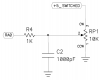
Attached is a schematic showing the voltage divider from the PICkit1 board used to test the analog input by providing varying voltage (I think this is accurate!! Correct me if I'm wrong).
1. Why doesn't the circuit try to flow 5 amps (i=v/r =5V/1ohm =5A) of current to ground when you have RP1 turned all the way down (ie. 1ohm resistance or less)? Isn't this a short circuit?
2. This leads to my second question: When designing circuits (at the moment i'm using a PIC12F675), how much current should you aim to feed into the IO ports when used in analog mode? For example, here the resistance between +5V and RA0 is between 1K and 11K which according to Ohm at 5V drop would be between 5mA and 0.5mA. Or isn't this how it's calculated?
3. What about when the port is in digital mode? I think this is called TTL mode - how much current should you feed them? In other words, what size resistor should be used for a switched input? 1K / 4.7K / 10K?? Confused! Pull up, pull down, can somebody please explain!
Thanks,
David")
1. Why doesn't the circuit try to flow 5 amps (i=v/r =5V/1ohm =5A) of current to ground when you have RP1 turned all the way down (ie. 1ohm resistance or less)? Isn't this a short circuit?
2. This leads to my second question: When designing circuits (at the moment i'm using a PIC12F675), how much current should you aim to feed into the IO ports when used in analog mode? For example, here the resistance between +5V and RA0 is between 1K and 11K which according to Ohm at 5V drop would be between 5mA and 0.5mA. Or isn't this how it's calculated?
3. What about when the port is in digital mode? I think this is called TTL mode - how much current should you feed them? In other words, what size resistor should be used for a switched input? 1K / 4.7K / 10K?? Confused! Pull up, pull down, can somebody please explain!
Thanks,
David