Continue to Site

Welcome to our site!

Electro Tech is an online community (with over 170,000 members) who enjoy talking about and building electronic circuits, projects and gadgets. To participate you need to register. Registration is free. Click here to register now.

  • Welcome to our site! Electro Tech is an online community (with over 170,000 members) who enjoy talking about and building electronic circuits, projects and gadgets. To participate you need to register. Registration is free. Click here to register now.

Video feeding,interesting

Status
Not open for further replies.
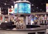
This's interesting,mechanical scaning LED screen.A single column of RGB LEDs are placed along one generatrix of a cylinder.The cylinder rotates at a high speed and a cylinder screen is formed.Below is such a screen composed with three individual channels of video signal.Which all look really clear.

I think I know how to synchronize the scaning.A switch hall sensor and a precision division algorithm will provide sufficient accuracy for the LED column to synchronize while rotating.But how the heck did they feed the video into the rotor anyway?I've heard the video source are computers.Presumably they use VGA signals?3 channels of VGA signal involve up to 9 analogue channels,I seriously doubt if there's any way to feed them all into the rotor without distortion.I think the most probable solution they are using is bruh-ring structure.For modulated signal with only one channel,a laser beam along the axis is also possible.What're your ideas my friends? :roll:
 

Attachments

  • dynoscan.jpg
    dynoscan.jpg
    26.1 KB · Views: 987
I think the mechanical issues with that will be harder than the electrical ones.

What I would do is put all the electronics inside the cylinder, and feed it video through a vertical antenna running up the center (so the received signal doesn't change with angle). Then your electronics can read off a line of pixels to the LEDs on each angular step.

A hall effect sensor probably won't be fast enough to provide accurate synchronization (that thing will have to spin really fast), but you could use some kind of optical detection. Maybe one or more LED's on the outside, at the top or bottom, with a sensor spinning around on the cylinder. Then you could use a PLL with frequency division to derive a clock.
 
It's DynaScan (with an a). Here's the official website:
https://www.dynascanusa.com/

Here's a patent concerning the display:
https://www.freepatentsonline.com/6335714.html

They are using polarized filters for the 3D portion of the patent. They also use multiple sets of LED emitters (8 according to the patent diagram) which would reduce the RPMs required to prevent flickering.

After thinking about it a bit, polarized filters could be used to produce extremely crisp pixels on the left and right edges, which would normally be affected by the precision of the timing.

If a filter comprised of vertical strips of alternating polarizations surrounded the display (the width of each column being the desired pixel width), along with at least two sets of LED arrays with opposing polarization, then each LED bank could be changed while it was obscured by the opposing filter. Relatively speaking, that would provide a massive window in which changes could be made to the pixels, which would also allow them to occur serially.

Dan East
 
i_build_stuff said:
I think the mechanical issues with that will be harder than the electrical ones.
Can't agree more.


What I would do is put all the electronics inside the cylinder, and feed it video through a vertical antenna running up the center (so the received signal doesn't change with angle). Then your electronics can read off a line of pixels to the LEDs on each angular step.

What do you mean by antenna?A wireless transmission or some sort of sliding contactor?Three video channels make a great amount of data stream,I think a parallel data transfer is inevitable.There's no time for encoding and decoding the video singal because of the mechanical structure,which makes it neccessary to keep the input video signal as simple as possible.I drew a scheme with MSpaint and attached it below.Do you think it will work?Or could please you offer a better solution for multi data line connection?


A hall effect sensor probably won't be fast enough to provide accurate synchronization (that thing will have to spin really fast), but you could use some kind of optical detection. Maybe one or more LED's on the outside, at the top or bottom, with a sensor spinning around on the cylinder. Then you could use a PLL with frequency division to derive a clock.

um...I just searched the web to check the switch hall sensors response.it will respond within one microsecond.A speed of 3600rpm gives a refresh rate of 60fps,which is 21,600 degrees per second.The time lag in response will cause an angular error of less than 0.02 degree,which I think is still tolerable for the horizontal positioning.The diameter of the cylinder is over 4 feet.So the perimeter will measure up to 13 feet.Placing a magnet along the perimeter on the static frame and a switch type hall sensor at the tip of the rotor will provide minimum waveform width when the sensor passes by the magnet.An optical solution could provide better accuracy,but I would choose wider gap between the emitter and the sensor for the opaque tip to go throung.Because mechanical variation may deform the structure to make the tip hit the optical unit.

However the PLL method is cool.When the horizontal resolution is Two's power,this hardware angular divider is perfect for saving CPU labour.
 

Attachments

  • scheme.gif
    scheme.gif
    9.3 KB · Views: 915
Over Christmas I noticed a similar technology at my uncle's. He had a clock that consisted of a tiny arm that would oscillate back and forth, creating a virtual LED matrix in thin air. I found some pics here:
**broken link removed**
Scroll down to the second set of images.

That got me interested in trying a full-color version driven by a pic (which I haven't gotten around to yet). It may be a simpler hardware model to start with, since you could run very thin wires directly to the LEDs. Of course RGB LEDs should be utlilized for full color. :) A couple things I would try right off would be a rainbow (wouldn't even require changing the LEDs real-time). The next step would be some pretty gradients by changing the intensity from one end of the cycle to the other.

The software to drive it would be very similar to a cylinder version. Actually it would be slightly more complex, because you would have to draw the display in reverse during the backswing of the arm.

Dan East
 
Well I think the planar structure is the predecessor of the cylinder one.Actually I've seen a discal scaning clock on a local forum a couple of years ago.It gave me a great shock as the idea was novel!

Then there came those swing sticks which people wave in hand in concerts to display "I Love U" etc. The clock in the link you provided works same way the sticks do.I don't fully appreciate the idea of adding a motor to it coz it wastes too much power.As for the revolving design,it's fine.

I broght up this thread because I'm building my own tiny cylinder display myself.It was started over a fortnight ago before I ran into DynaScan ads.The pictures they had there shock me again.I thought it was impossible to feed massive video signal into the rotor.But they made it!And they gave it 3 video channels at a very high resolution.It was back then that I realized how simple my stuff was.

I mainly use AVR for my projects and sometimes PIC.They are both good microcontrollers.In my tiny cylinder display project I chose ATmega8L as the processor.All contents to be displaied are stored in a memory on the board.The display resolution is 128 by 16.The nominal cylinder has a diameter of 90mm and altitude of 33mm.

I placed R,G and B columns separately around the cylinder with 120 degrees' spacing.This is because I couldn't find LEDs with RGB integrated in one core,and it's really difficult to make a pixel look white by squeezing all three colors together - the cylinder is so small that size of the LEDs is not neglectable.I made a mistake while designing the circuit.Three pairs of shift registers(74HC595 SOP) are used to control three colors.The SDA,SCLK,RCLK of these three pairs are shared.I mistook the G pin of HC595 as a -CS pin.So the fact is,when I send out data to the Red column and hold Green&Blue's G pins high,the Red data still corrupts G&B registers.You don't see it because G pins shut down the G&B output.This mistake made it impossible for me to light all three colors simultaneously without affecting each other. :oops:

The PCBs weren't made locally,but they're just about to arrive tomorrow.I will take pictures if you are interested.
 
Sure, I'd love to see some pictures. Sounds like you'll be moving onto some hi resolution stuff soon.

Dan East
 
Dan East said:
Sure, I'd love to see some pictures. Sounds like you'll be moving onto some hi resolution stuff soon.

Dan East

Yup,I am thinking about improving the resolution significantly.But before that I have to finish the current project.

Anyway I'm doing this for fun.I'll share information with everybody here after it's done.

My boards arrived.I took a pic of them together with my motor and Li+.More to come after some soldering :wink:
 

Attachments

  • pcb_133.jpg
    pcb_133.jpg
    35.6 KB · Views: 867
This looks good, just the other day I found the remains of my original spinning display in the workshop and was wondering what if I used a strip each of red green and blue rather than just a strip of red, and couldn't find anything online.

Do you think there will be any advantage to using separate LEDs for each colour rather than RGB LEDs?
 
Well, as Alex mentioned, if you use separate LEDs and isolate each color in a separate array on the spindle, then each LED can illuminate the exact same point in space, which should provide really crisp white pixels without any individual color components bleeding around the edges.

With RGB LEDs, the three colors are physically offset from one another by 1mm or so, so it would not be possible to achieve the same sharpness. My Yaesu VX-7R has an RGB LED that you can program for any 24 bit color, and with low intensity colors you can clearly see the individual emitters in the LED. With bright colors it all seems to blend together better.

Dan East
 
What resolution are you going for?

I forget what the res on those HD-DVD's is, but it was somewhere around 2000 x 1000. If you had that in 24 bit color, with 3 channels, at 25 frames/sec, it would take about 3.6GBit / sec to transmit (or 1.8GHz of analog BW). That would be do-able with a round waveguide running up the center, in a mode where there is no current along its axis (I think the TE modes are like that).

Otherwise, you might consider using the brushes, but not actually making contact (instead, capacitively couple the signal in through an outer ring that's very close to the inner ring). Unless the video will be digital (with error correction), regular brushes will probably be too noisy.

This might also be a good time to think about video compression...
 
ChriX said:
Do you think there will be any advantage to using separate LEDs for each colour rather than RGB LEDs?

:? I whish I didn't have to use separate LEDs! I am using them because,as I mentioned above,I could find RGB integrated LEDs.I will keep hunting when I go to cellphone repair stores.
 
Dan East said:
My Yaesu VX-7R has an RGB LED that you can program for any 24 bit color, and with low intensity colors you can clearly see the individual emitters in the LED. With bright colors it all seems to blend together better.

This is valuable info.I never seen such type of LED,so I had no idea what it will actually look like.Now I wonder how the sharpness is ganna be when we look at the pixels from a certain distance away?I would still prefer using RGB integrated LEDs because separating colors results in a big problem that will significantly affect the display efficiency.

Say my display was initially designed to have a 128 by 16 resolution.And I divide one spin cycle into 128 sectiongs to provide each column of pixels with accurate timing.The good thing about using 128 as the horizontal pixel count is,as two's power,it can be easily fetched either by shifting timer value 7 bits to the right(when a software cycle division is implemented) or by a hardware 128x PLL as suggested earlier by i_build_stuff(when a hardware frequency multiplication is implemented).After all 128 saves much work than other ordinary numbers.Not to mention it just fits the width of 16 ASCII characters.

However 120 degrees' spacing of the three individual colors forced me to make corrections to this number.As the circle is divided evenly into 3 parts,the horizontal pixel count must be the multiple of 3.This is obvious when you distribute any number of pixels along this 120 degree arc.Whatever this number along this arc,the total pixel count is 3 times of it.

126 can be divided exactly by 3.The cost is sacrificing a lot more machine cycles on the 16 bit/ 8 bit software division.There are 2-machine cycle hardware multiplication instructions in ATmega8L,but not hardware division instructions.I won't use pre-written division subroutines.Instead I will optimize it for the fixed divisor(126).I hope this optimized division doesn't cost me too much time.

As I previously described,I attempted to use the -G pin of 74HC595(pin 13) as a -CS pin.I thought this would give me control over the data inlet of each pair of 595.However after the PCB order was placed I found out I was wrong,and in this way only one color can be illuminated at a time.Because all the register pairs will be updated when I attempt to update any single pair.Now that I have thought into the whole scheme,I wish I had placed all 6 registers in serial....
 
i_build_stuff said:
What resolution are you going for?

I forget what the res on those HD-DVD's is, but it was somewhere around 2000 x 1000. If you had that in 24 bit color, with 3 channels, at 25 frames/sec, it would take about 3.6GBit / sec to transmit (or 1.8GHz of analog BW). That would be do-able with a round waveguide running up the center, in a mode where there is no current along its axis (I think the TE modes are like that).

Otherwise, you might consider using the brushes, but not actually making contact (instead, capacitively couple the signal in through an outer ring that's very close to the inner ring). Unless the video will be digital (with error correction), regular brushes will probably be too noisy.

This might also be a good time to think about video compression...

I'm currently working on extremely low resolution,126*16 as mentioned above :lol:

Yes,when it come to high resolution like the HD-DVD,tremendous data flow will be overwhelming.I tend to use full digital interfaces.And I think your suggestion of capacitive coupling is very brilliant.It avoids attrition,so then rings and brushes don't wear out as the whole stuff ages.And reduces the load on the motor.

As for video compression,a hardware resolution will be preferable.I think it will be really effective on the data transmission.
 
Mouser carries a few RGB LEDs.

Surface mount, "Water clear" lense, 120º viewing angle, 2.8 x 3.2 mm:
Mouser product page
Data sheet

Surface mount, "White diffused" lense, 120º viewing angle. 5 x 5 mm:
Mouser product page
Data sheet

This is in a larger DIP-6 package, which would be really good for experimenting on a breadboard:
Mouser product page
**broken link removed**

Here's a through-hole version (costs 3x as much as the first two), 5mm, 30º viewing angle:
Mouser product page
Data sheet

I think the first one would suite your project best, because its form factor is ideal for stacking in a tight column, plus the wide viewing angle will help keep the image from fading off as the LEDs face away from the viewer on the edges of the display.

Dan East
 
Thank you,Dan.I've downloaded all the datasheets.And I'm taking a close look at them.I think the price is good,except that it will cost me much on shipping,because I live in China.I think I can also use the parameters as a template and look for similar LEDs here.

I have finished soldering part of the system and I took pictures of the boards.The critical issue is to balance the rotor.It's really difficult for me,especially when I'm building such a thing for the first time.Three arcs of solder plate areas were drawn when I was designing the rotor hub.By attaching excessive solder,I can adjust the C.G as close to the geometric center as possible.It's an electronic device after all.Assigning weight evenly through the whole cylider in the designing phase is extremely difficult.And it's impossible to make a rotor of absolute symmetry around its axis.

There're a few other problems that I have to resolve.I will get rid of them one by one.Here are two pics I just took:
 

Attachments

  • assembly-1.jpg
    assembly-1.jpg
    44.2 KB · Views: 703
  • assembly-2.jpg
    assembly-2.jpg
    26 KB · Views: 694
ChriX said:
Looks like it is coming along well, keep us updated!

:) Sure,I've got only 3 days left to stay home.Then I'll pack my stuff and head for school which is 2500km away.However I will keep working on it and of course,keep updating info here.
 
Status
Not open for further replies.

New Articles From Microcontroller Tips

Back
Top