Lyallbay04
New Member
Hey guys,
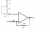
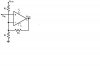
I'm converting a analogue to digital signal using an op-amp to make a Schmitt trigger. It needs to be non-inverting, so i just change Vin to the positive feedback, right? But also how do i find the Upper and lower threshold and what dictates how far a part these thresholds have to be apart? Does it depend on the amount of noise that the circuit has.
Thanks
")