toysareforboys
New Member
Hello! This is my first time here. I apologize in advance for the long post/questions.
I've built in the trunk of my car a 16.2v maximum capacitor bank (500 farads) and installed two 14v XSPower D1400 batteries (charge at 16v, not connected to anything yet), in addition to the factory battery (it comes in the trunk stock). I wish to run my aftermarket car stereo amplifiers at 16v off the capacitor bank and D1400 batteries but the rest of the car at the stock voltage level off the factory battery/charging system.
My amplifiers draw 230amps total (at 12v ish, not sure if they are any more efficient at 16v).
Because my car (2007 Chevy Cobalt SS/SC) uses an ECU controlled alternator that's impossible to swap without getting a check engine light (not possible to pass emissions check with SES light here) and it's not possible to install a second alternator, my plan to make my 16v dreams come true is:
1. To use 100 of these: **broken link removed**
2. Replace the potentiometer with a fixed resistor (to make sure all the output voltages match perfectly). No idea how to calculate which resistor would get me bang on 16v output. And I need really tight regulation too seeing as my cap bank is maximum 16.2v, but I've read that the regulation on those boards is really good.
3. Attach all 100 of them to a single really nice heatsink.
So, my questions for the more electronically inclined people:
4. Is this the most efficient/cost effective way to provide lots of power to the 16v bank from my stock 12v system?
5. I assume there wouldn't be any issues hooking up 100 of them in parallel, I'd use bus bars for all the input and output power, and the supplier said it's NOT a shared ground system, so that'd be four bus bars.
6. I've read that the LM2577 needs a minimum of a 2v difference between the input and output, so while my car is running at say 14.4v there will be less than a 2v difference to 16v. Not sure if the XL6009 suffers the same problem.
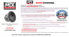
7. How could I effectively attach all 100 of them to a single large aluminum heatsink to cool the main XL6009 chip? Here is what the underneath of the circuit board looks like, no thermal path to cool the back of the XL6009 chip
**broken link removed**
So I assume I'd have to use aluminum square rod to cut a chunk from that would go from the front of the XL6009 to the heatsink to provide the thermal path. They sell these little heatsinks dirt cheap, but not sure that's enough heatsinking for my likes: **broken link removed**
One project I saw they actually cut out the circuit board underneath the XL6009 chip and pushed the chip down so it was flush with the bottom of the circuit board then used a thermal pad and mounted it to a heatsink, looks like it'd work awesome but not sure if there's any traces or anything on that board that might prevent doing that. And to do that to 100 boards would probably get annoying quick.
Any insight you could provide would be greatly appreciated.
-Jamie M.
I've built in the trunk of my car a 16.2v maximum capacitor bank (500 farads) and installed two 14v XSPower D1400 batteries (charge at 16v, not connected to anything yet), in addition to the factory battery (it comes in the trunk stock). I wish to run my aftermarket car stereo amplifiers at 16v off the capacitor bank and D1400 batteries but the rest of the car at the stock voltage level off the factory battery/charging system.
My amplifiers draw 230amps total (at 12v ish, not sure if they are any more efficient at 16v).
Because my car (2007 Chevy Cobalt SS/SC) uses an ECU controlled alternator that's impossible to swap without getting a check engine light (not possible to pass emissions check with SES light here) and it's not possible to install a second alternator, my plan to make my 16v dreams come true is:
1. To use 100 of these: **broken link removed**
2. Replace the potentiometer with a fixed resistor (to make sure all the output voltages match perfectly). No idea how to calculate which resistor would get me bang on 16v output. And I need really tight regulation too seeing as my cap bank is maximum 16.2v, but I've read that the regulation on those boards is really good.
3. Attach all 100 of them to a single really nice heatsink.
So, my questions for the more electronically inclined people:
4. Is this the most efficient/cost effective way to provide lots of power to the 16v bank from my stock 12v system?
5. I assume there wouldn't be any issues hooking up 100 of them in parallel, I'd use bus bars for all the input and output power, and the supplier said it's NOT a shared ground system, so that'd be four bus bars.
6. I've read that the LM2577 needs a minimum of a 2v difference between the input and output, so while my car is running at say 14.4v there will be less than a 2v difference to 16v. Not sure if the XL6009 suffers the same problem.
7. How could I effectively attach all 100 of them to a single large aluminum heatsink to cool the main XL6009 chip? Here is what the underneath of the circuit board looks like, no thermal path to cool the back of the XL6009 chip
**broken link removed**
So I assume I'd have to use aluminum square rod to cut a chunk from that would go from the front of the XL6009 to the heatsink to provide the thermal path. They sell these little heatsinks dirt cheap, but not sure that's enough heatsinking for my likes: **broken link removed**
One project I saw they actually cut out the circuit board underneath the XL6009 chip and pushed the chip down so it was flush with the bottom of the circuit board then used a thermal pad and mounted it to a heatsink, looks like it'd work awesome but not sure if there's any traces or anything on that board that might prevent doing that. And to do that to 100 boards would probably get annoying quick.
Any insight you could provide would be greatly appreciated.
-Jamie M.