Continue to Site

Welcome to our site!

Electro Tech is an online community (with over 170,000 members) who enjoy talking about and building electronic circuits, projects and gadgets. To participate you need to register. Registration is free. Click here to register now.

  • Welcome to our site! Electro Tech is an online community (with over 170,000 members) who enjoy talking about and building electronic circuits, projects and gadgets. To participate you need to register. Registration is free. Click here to register now.

Use of LM2917 freq to dc converter?

Status
Not open for further replies.

potoole64

New Member
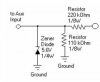
Using an LM2917 freq to dc converter: (https://www.electro-tech-online.com/custompdfs/2008/11/LM2907PDF.pdf). (2917 IS ALSO COVERED IN THIS FILE) Converting pulses to dc voltage, then outputing that dc volatge to a TLC0831 analog to digital converter (https://www.electro-tech-online.com/custompdfs/2008/11/tlc0831.pdf). Output from A/D is then read and stored in a Parallax BS2 microcontroller, which uses a PIC16C57C as its main chip.

Using an oscilloscope, I've noticed that the output from the LM2917 is not very steady, it comes out in waves that slope upward and downward at about the same rate as the input pulses, which are less than 100pps.
How can I make the 2917 output smoother?
A filter capacitor somewhere?

I tried putting a 10MFd cap. across the output, and I think I ruined the 2917 by doing so. Now I get nice square wave pulses as an output. Perhaps I shouldn't have done that. :eek:

Patrick
 
The LM2917 doubles the frequency, rectifies it then smooths the DC with a capacitor. The amount of ripple should be fairly low unless the input pulses are at a very low frequency.

The output is a transistor that is destroyed by the capacitor at the output you added.

Maybe you did not add the correct filter capacitor in the circuit.
 
Thanks, Unka Scrooge.
My mistake. I managed to get the thing working again; I found a loose ground connection. Now it works ok, except for voltage restrictions as a result of the BS2 5volt enable/disable pulses to the 0831 a/d. If the output from the lm2917 reaches or goes over the 5 volt pulse, a conflict ensues. I will need to lower the values of CI (pin 2) and R1(pin 3) of 2917 So the output voltage won't go over 5 volts. I hope that will take care of the conflict.:confused:

Patrick
 
Now it works ok, except for voltage restrictions as a result of the BS2 5volt enable/disable pulses to the 0831 a/d.

Do you really need to log voltages with the BS2? Why not just use the BS2 to count the frequency of the input signal directly?
 
saturn1bguy asked:
Do you really need to log voltages with the BS2? Why not just use the BS2 to count the frequency of the input signal directly?

I tried counting pulses with the BS2. It worked sorta-kinda. My original intent was (still is) to count or measure the pulses coming from the ignition of my Harley Sportster, from the same point that the tachometer is fed, but after the voltages were reduced to the counting circuitry, to about 4 volts. Those pulses come from the primary side of the ignition coil (transformer), and are a little ragged. (The BS2did a poor job of counting the pulses that came directly from the ignition coil. )So I tried to clean them up with a Schmitt trigger, which didn't work as expected. I tried clippers and clampers and a monostable MV to get those pulses just right for the BS2, but the BS2 seemed to get mixed up easily in the counting process and I ended up with counts that didn't make any sense and didn't follow anything proportionate to the input counts. So I've given up on that for the time being, maybe I'll go back to it.

Now I'm trying to convert the pulses to a varying dc voltage using the LM-2917, which is how some tachometer circuits operate (LM2917 was intended for that, I guess). Then, using a ADC-0831, convert the varying dc to digital, store that data on BS2's EEPROM, then bring that stored data into my desktop PC so I can monkey around with the data on a spread sheet or some other software. I want to develope a torque/horsepower curve (whew)

There are other ways of doing it, too. Using magnets with a Melexis magnetic detection circuit. I'll probably try that method out someday.

It's a long learning process, I'm a retired guy with some time on my hands, and learning to work with microcontrollers has become an interesting hobby. It keeps an old man busy, and out of his wife's hair.

Patrick
 
saturn1bguy asked:
Do you have any schematics of the circuitry you're trying to interface with, and how exactly were you trying to count the pulses?

Wow, that's a daunting task, but I'll try. It all took place over a long period of time, I won't say how long; there was a lot of "thinking time" involved.
I used the Pbasic "count" command of the BS2.

Pulses from the ignition go from 12v to gnd(0v), and are ragged at top end. So there are positive and negetive portions to the pulses. The neg. part, if I remember, is about 5ms in length while the pos part varied according to RPM. (8 to 15ms). At first, I tried using the short neg. pulses, since they are flat on the 0v bottom, but just couldn't get that to work.

(1) Motorcycle ignition system: Take output from minus (-) end of primary side of xfmer.(see attachment)

(1) Voltage divider, which is connected to ignition output (see attachment), but couldn't use zener; resistances restricted current to the diode making it inoperable. (Got it from :)
Stephen Mullen
www.Nightrider

You need to remember that the cam rotates at half speed and that is what the ignition breaker plate is attached to.

With a single fire coil, you get one ignition event every 720 degress of engine rotation (or every 2 RPM). With a typical OEM H-D dual fire coil, you get two ignition events every 720 degrees (or one per RPM). If you read the (-) post on the coil, you will get the voltage switching between 0 and +12VDC (or up to 14V with the engine running due to alternator output). The only AC voltage produced on your HD is the direct output from the alternator, prior to the voltage regulator.

(2) Schmitt trigger (http://www.uoguelph.ca/~antoon/gadgets/555/555.html) Towards bottom of page under SAMPLE CIRCUITS. This seemed to work at first, but didn't; BS2 missed counts or added counts.

(3) Monostable MV, (555 and 556 Timer Circuits)trying to get one long pulse that wouldn't allow interference from anything in between. Couldn't get that to work at all from the motorcycle.

(4) Junky hand drawn attachment of prementioned ckts together. (see attachment)

(5) Clipper circuitry used after failure of Schmitt and mono. MV. (attachment) BS2 miscounts, gets too many other "spurious signals ? (Army days)" mixed in

(6) Parallax BS2: (**broken link removed**)

That's enough
Patrick
 

Attachments

  • nitrdr_ckt.jpg
    nitrdr_ckt.jpg
    7.7 KB · Views: 456
  • IMG_0004.pdf
    820.2 KB · Views: 438
  • IMG_0003.pdf
    294.1 KB · Views: 284
  • IMG_0001.pdf
    439.2 KB · Views: 299
I think you want to stay away from the coil in any case.

Looking at your ignition diagram, the computerized ignition module has two inputs, one output, and 12V power. The output switches the coil primary to give you spark, I'd stay away from that. The vacuum input switch simply selects one of two spark-advance profiles, so this sensor is not useful to to you here. That only leaves the cam position sensor to pick off a useful signal for your BS2 to count. It has three wires, I would scope them out. Once you've done that, you'll better know how to proceed to condition its signal for the BS2.

On the BS2 side, you already know the count command, fine. It seems the most appropriate for your task, once the input is properly conditioned.
 
Hi there,

Just in case you get back to this, i thought i would offer a tip
about reading the pulses more directly.

The coil primary will look like a pulsing signal with some oscillation.
This might look very strange, but it's just the way coils respond
to pulsing drives and it's nothing too strange i can assure you.
The pulsing is caused by the ignition timing, and the oscillation
is caused by what is known as the "Free Oscillation Frequency"
of the circuit, also sometimes called the "Ring Frequency" or the
"Ringing Frequency". The ring frequency is a good name i think
because when this happens the circuit is often said to 'ring'.
It's a natural occurrence and happens in many circuits with
coils.
The only thing we have to know really is that the ring frequency
is going to be higher than the pulsing ignition frequency, and
that the ringing, if filtered, turns into a ramping signal.
The idea then is to filter the signal from the coil primary with
a low pass filter and then use a comparator with hysteresis
so that it detects when the filtered signal ramps up and then waits
for the signal to drop back down to a rather low level before
it starts to look for another ramp.
The whole circuit might work out to a simple one, with a resistor
and capacitor for the low pass filter, and a LM339 comparator
section designed with some hysteresis (a little positive feedback).
That shouldnt be that difficult to build, however, there is a catch.
The low pass filter has to be tuned so that it can pass the
lower ignition frequency while filtering the higher ring frequency.
This might require trying several values of resistors and or caps.
Since a filter like this can also be specified by its RC time constant,
and the RC time constant is simply the value of the R times the
value of the C (ohms and farads), all we have to do is start with
a rather low value of RC time constant (also called TC for short)
and work the value of the cap up a little at a time while seeing
if the uC starts to pick up a reasonable data stream.
Alternately, if a scope is available, we can look at the waveform
and pick R and C so that the rings get filtered out but the pulses
do not.
Perhaps start with a 10k resistor and 0.001uf cap, then try
a 0.01uf cap, then 0.1uf cap. If that doesnt work try 20k
and those same cap values, then 50k, etc.
Eventually the right RC time constant will be found and the
comparator will only pick up the ignition pulses.
I wouldnt go lower than about 5k on the resistor and higher
than 1 megohm i think when doing this.
If you know your ignition frequency min and max that would
help too as we can get a better starting value for R and C.
 
Thanks MrAl,
Lots of interesting information in your message. I have observed the ignition pulses with my scope, and have seen the ringing. I think I tried a circuit similar to the one you suggest:
The whole circuit might work out to a simple one, with a resistor and capacitor for the low pass filter, and a LM339 comparator section designed with some hysteresis (a little positive feedback). That shouldnt be that difficult to build,
But probably didn't pursue it far enough, as you state:
all we have to do is start with a rather low value of RC time constant (also called TC for short) and work the value of the cap up a little at a time while seeing if the uC starts to pick up a reasonable data stream.
I sort of let it go after the first couple of tries.
I've also tried a clipper, which cut off the ringing tip of the pulse, in fact I still use it with the LM2917.
The BS2 continued to miscount the pulses even after my clean up detail, but counting the pulses (pulses per second) seems to be the clear cut way to get to an RPM/torque/horsepower curve.

thanks for the help
Patrick
 
Last edited:
I need to mention that getting pulses from the Sportster requires that I hook circuitry up to the ignition system, then fire up the bike, and rev the engine up time after time. This not only gets the engine quite hot, but probably annoys the crap out of my neighbors.
I made a simple ckt. in house that puts out a similar pulse as the bike's ign., and the BS2seems to work quite well with it. I try out my test ckts, using that as a stand in for the ign., and things work, but the ckts don't want to work on the bike; the BS2 still miscounts when connected to test ckt. and bike ign.
 
but counting the pulses (pulses per second) seems to be the clear cut way to get...

Yes, but which pulses?

Have you not scoped out your cam position sensor yet? It may give you a signal that's easy to interface compared to the ringing coil signal. Why do it the hard way when they may be an easy way?
 
Thanks MrAl,
Lots of interesting information in your message. I have observed the ignition pulses with my scope, and have seen the ringing. I think I tried a circuit similar to the one you suggest:

But probably didn't pursue it far enough, as you state:

I sort of let it go after the first couple of tries.
I've also tried a clipper, which cut off the ringing tip of the pulse, in fact I still use it with the LM2917.
The BS2 continued to miscount the pulses even after my clean up detail, but counting the pulses (pulses per second) seems to be the clear cut way to get to an RPM/torque/horsepower curve.

thanks for the help
Patrick

Sure no problem. Also, if you can provide some scope shots of the
ring waveform and at what rpm i could suggest a proper filter too
that would save time.
 
You have a motorcycle without a muffler? Shame on you.
Loud pipes save lives, Unka Scrooge; If the cage drivers can't see me coming they can hear me, hopefully while they're talking on cell phones, lighting a cigarette, and reading messages as they roar down the streets and highways, tailgating and passing every vehicle in sight even at speeds well over the speedlimit. Just kiddin, thanks for the message. (The pipes have baffles, but you ought to go to Sturgis if you want to hear loud bikes)


saturn1bguy asked:
Yes, but which pulses?
Have you not scoped out your cam position sensor yet? It may give you a signal that's easy to interface compared to the ringing coil signal. Why do it the hard way when they may be an easy way

I believe that will be my next move. I might have thought of that before, but didn't know if I could do it, or something, but now it sounds like the thing to do. The Harley manual gives directions on how to make a test harness that will connect to the speed sensor. So I think that I will try that route. I think the speed sensor is a Hall effect sensor, and will give off square wave pulses. I was concerned that jumping off from those sensors would damage them, but probably not. Thanks for the info.

MrAl:
if you can provide some scope shots of the
ring waveform and at what rpm i could suggest a proper filter too
that would save time.

I might try that, too. I think I did take a picture, but don't remember where it is. I have to drag the scope out to the cold North Dakota garage, and fire up the bike to do that.

Thanks to all for the information and help.
Patrick
 
The bikes in my city can be heard many miles away. They don't have mufflers or baffles. Just chrome pipes with a war coming out of them.
 
Status
Not open for further replies.

New Articles From Microcontroller Tips

Back
Top