Continue to Site

Welcome to our site!

Electro Tech is an online community (with over 170,000 members) who enjoy talking about and building electronic circuits, projects and gadgets. To participate you need to register. Registration is free. Click here to register now.

  • Welcome to our site! Electro Tech is an online community (with over 170,000 members) who enjoy talking about and building electronic circuits, projects and gadgets. To participate you need to register. Registration is free. Click here to register now.

use a pushbutton to control a light

Status
Not open for further replies.

ptfuzi

New Member
hi, this is my first post,
i'm from portugal and i can speak english a bit, i don't have many knowledge of electronics and i came here because i believe someone can help me..

i'll try to explain what i want to do..

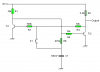
i want to control a light (it can be a led), using a pushbutton like this for example..

**broken link removed**

and i don't have any idea how to use this. i want that when i click the button the light turns on, and when i click again it turns off..
i want this kind of button and not an switch because i want that the light turns off when i cut the power, and when i turn the power on the light doesn't turn on until i click the button.

please apologise for my bad english, but i hope someone can understand and help me.

thanks in advance!
 
complex?? thats about as simple a circuit you can get...

the CD4027 Dual JK flip flop

yup thats it in the pic above
 
Last edited:
Or you could use a couple of transistors.

I'd go with the IC myself but if it's high voltage then I'd use transistors.

EDIT:
This is more complicated.:D

You don't need the relay and transistor on the CD4027 if all you're going to do is drive an LED.
 

Attachments

  • Two transistor l&#97.PNG
    Two transistor l&#97.PNG
    1.5 KB · Views: 218
Last edited:
Or you could use a couple of transistors.

I'd go with the IC myself but if it's high voltage then I'd use transistors.

EDIT:
This is more complicated.:D

You don't need the relay and transistor on the CD4027 if all you're going to do is drive an LED.

ok..

first i want to know if i use 12v there will be no problem (because pics say 9v)..

it's to control some leds..but i think the led quantity is not a problem (you know better than me), it's to control two of this
https://img.auctiva.com/imgdata/7/8/5/6/1/6/webimg/279912637_o.jpg

and what's that symbol after the transistors and the capacitor??

thank you all:)
 
Last edited:
The circuit i posted can handle upto 15v so 12v will be fine.

I would suggest leaving the transistor in place and replace the relay with your leds.
 
ok..

first i want to know if i use 12v there will be no problem (because pics say 9v)..
Both these circuits will work from 12V.


it's to control some leds..but i think the led quantity is not a problem (you know better than me), it's to control two of this
https://img.auctiva.com/imgdata/7/8/5/6/1/6/webimg/279912637_o.jpg
It does matter.

How much current does it use?

and what's that symbol after the transistors and the capacitor??

thank you all:)
There are lots of symbols in the schematic, please give the schematic reference?

I'd recommend building the one with the CD4027 because it's easier to build and uses less power.
 
one led is: SMD 1210, 0.2W, 15LM.

i'll use 2x21 of these leds, i don't know the current

i'll use the first scheme

where it says "0.47nF" its a capacitor right?

i'll use transistor and instead of relay i'll put there my leds..

and i have another question, the leds go on place of the relay, and what i put this (inside the red circle) **broken link removed**
 
Last edited:
but i need to know too how many volts the capacitor is!
and if resistor is 1/2w?? or 1/4w?? or what?
thkx
 
Last edited:
It's 0.47µF which is 470nF

The symbol you've circled is the 0V or negative rail in this case.

You might need to reduce the value of the base resistor and use a higher current transistor if the LED current is higher than about 30mA.
 
cool!
now i only want to know how do i can know the led current?
it's possible to calculate using this data:

led is: SMD 1210, 0.2W, 15LM.
i'll use 2x21 of these leds
if it's higher than 30 mA it won't work at all??
 
Do you have a datasheet for the module?

The circuit, just needs a couple of modifications to work at higher currents.
 
datasheet? no...

but i will do every of first scheme, except i won't use relay, and it should work, right?
 
I'd make the following modifications.

This should be fine up to 200mA.
 

Attachments

  • LED ON OFF 4027..PNG
    LED ON OFF 4027..PNG
    1.7 KB · Views: 170
thank you!!! you're too kind!

once i have the items and try to mount successfully or not i'll let you know!!
 
You're right, I didn't spot that.
 

Attachments

  • LED ON OFF 4027.PNG
    LED ON OFF 4027.PNG
    1.8 KB · Views: 224
There are 21 LEDs. There is nothing to limit the current and we don't know if some of the LEDs are in series.
If the LEDs are all in parallel and use 20mA each then you need a darlington transistor that can switch 0.42A from a low current from the CD4027, not a little BC548 transistor.
 
I doubt they're connected in series, the circuit is designed for 12V operation so my guess is they're connected in 7 strings of three.
 
Status
Not open for further replies.

Latest threads

New Articles From Microcontroller Tips

Back
Top