Continue to Site

Welcome to our site!

Electro Tech is an online community (with over 170,000 members) who enjoy talking about and building electronic circuits, projects and gadgets. To participate you need to register. Registration is free. Click here to register now.

  • Welcome to our site! Electro Tech is an online community (with over 170,000 members) who enjoy talking about and building electronic circuits, projects and gadgets. To participate you need to register. Registration is free. Click here to register now.

up down counter

Status
Not open for further replies.

MrDEB

Well-Known Member
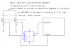
planning on using a disected mouse (wheel type) to determine wind directon using a PIC.
basically an up down counter.
starting with this code
Swordfish Wiki | SwordfishUser / DialEncoder browse
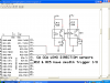
idea is to just use the two photo detectors and wheel (not wanting to unless necessary re engineer using the IC that is in the mouse. just the two detectors for the one wheel. (other wheel will be used for wind speed detection)
Thinking but I know its not right
if B0=1,1,0 and B1 = 0,1,0 then CW
if B1=1,1,0 and B0=0,1,0 then CCW
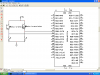
schemaic from another site
any suggestions?
oh yea the wheel will be driven at a 9 to one ratio (360 / 40(#of slots in wheel) which should add to accuracy . hopfully 1 degree
 

Attachments

  • pic opti.PNG
    pic opti.PNG
    68 KB · Views: 369
not right but thinking out loud

just piecing together thoughts on a simple encoder routine using mouse wheel (see above post)
I know its crude but maybe a start? Got to start somewhere. The privious link has an encoder routine but looks complicated but then mine is really crude but its my own work. maybe some additions it might work?
just need to detect degrees of rotation and direction. wheel has 40 slots and rotating at 9 to 1 ratio so 9 revolutions = 360 degrees or 1 rotation = 40 degrees. each slot = 1 degree
Code:
degrees = 0//number of degrees of rotations
// based on wheel having 40 slots and rotated 9 times for 360 degrees
Port B0=up
Port B1=down
While true
      up = 1
      down=0
      delay 1ms // allow wheel to rotate
      up=down Then degrees+1 // clock wise rotation
degrees = degrees +1
repeat
End 
While true 
      up = 0 
      down =1
      delay 1ms // allow wheel to rotate
If     up = down Then degrees+1//counter clock wise rotation
End  
degrees = degrees +1
If degrees = 359 Then degrees = 0
 
I have a problem with your wheel.You told your wheel has 40 slots.For a one full rotation it will count 40 counts?That means 40 Degrees? Ok you have mentioned that.Detecting the wheel direction is the hardest part.Will see what we can do.
 
Last edited:
FLOW CHART
for
AIR CANNON


WIND DIRECTION :
zero for barrel direction –
read rotation direction – CW or CCW
count # of rotations – CW or CCW > 0 but less than 359
display on LCD
WIND SPEED:
get data of # of rotations per TIMED interval
calculate wind speed based on calibration.(drive at set speed
and note data readout)
Display on LCD

TANK PRESSURE pressure transducer outputs ADC signal
0-5volts, 100 psi = 5 volts or 2mv = 1 psi?? check
data displayed on LCD

MUZZLE VELOCITY: get timed interval of two IR emitter detector pairs1 foot apart
timing starts on first opti pair interrupted (HIGH to LOW)
timing stops at second opti pair interrupted.(HIGH to LOW)
need to compute calculations for FPS using timed interval.
 
wind direction sensors

schematic of planned wind direction sensors using a mouse wheel and IR detectors (no IC from mouse)
using RC5 & ^ as they are schmidt trigger I/O ports (shouldn't need 74hc14?)
right way to go, I don't know??
 

Attachments

  • wind direction.PNG
    wind direction.PNG
    65.8 KB · Views: 411
basic circuit idea

for determing CW or CCW direction then count degrees of rotation
weather this is doable?
 

Attachments

  • up down counter.PNG
    up down counter.PNG
    31.4 KB · Views: 393
Quadrature decoding for direction of rotation and count will work...but...how are you going to establish you initial direction? Maybe manually hold the wind vane, pointing north, and have a "set" button to zero your direction counter.

Ken
 
THATS exactly my plan
place behind the cannon in line with barrel aimed at target.
release the wind vane as it is locked until pointed at target (reference point)
 
web surfing and find info

have2 data lines input to PIC
have interrupt at rising edge of say A input
in interrupt handler check state of B input
thought about adding IF A = B --but I only need to count the rising edge of one input until goes high again.
my recvised code. I know it isn't right but I am trying. one of them learn by doing kinda people.
Code:
Port B0=A        //A input
Port B1=B    //B input
While true
      A =1and B=0
      until A=0 and B=1
      CW=CW+1
end 
While true
      A =0and B=1
      until A=1 and B=0
      CCW=CCW+1
end 
// add if A = B then return to the first WHILE TRUE routine??
 

Attachments

  • ab wave forms.PNG
    ab wave forms.PNG
    71 KB · Views: 240
Quadrature decoding for direction of rotation and count will work...but...how are you going to establish you initial direction? Maybe manually hold the wind vane, pointing north, and have a "set" button to zero your direction counter.

Ken

I would put a 3rd optical sensor on the rotor, so it triggers at only one posiiton in a rotation (say North) and just use that to reset the count. The mouse has 4 sensors in it so he has a spare couple of opto sensors.
 
code progressing but ??

keep getting END EXPECTED error about the interrupt
still trying to get the hang of this.
Code:
Device = 18F452
Clock = 20
 
// some LCD options...
#option LCD_DATA = PORTB.4
#option LCD_RS = PORTB.2
#option LCD_EN = PORTB.3
 
// import LCD library...
Include "LCD.bas"
Include "utils.bas"
Include "ISRTimer.bas"
Include "convert.bas"        
 

Dim
    up As PORTA.0,
    dw As PORTA.1,
    
    RBIF As INTCON.0,
    RBIE As INTCON.3
Dim CW As Word,
    CCW As Word 
 
// Start Of Program...
SetAllDigital
ADCON1 = %00000110
  
Input(up) 
Input(dw)                          // Make the Hall-Effect sensor pin an input

DelayMS(150)                                 // Allow the LCD to warm up
 
Cls                                          // Clear the LCD, and display
WriteAt(1,1,"degrees rotation")                     //   default information
 
                                 // Create an infinite loop
 
                                // Reset PreScaler register
Interrupt PORTA0_Change()
end
    Save(0)                                   // Save the system variables
    If RBIF = 1 Then            // Check if the interrupt was a PORTA change
    RBIF = 0
        WREG = PORTB            // Be sure to read the contents of PORTB to
  EndIf
  end interrupt
    Restore                             // Restore the system variables
                                             //  clear the missmatch
 
        // PORTB 7:4 has changed, do what you want here...
          
While true 
          
//interupt routine


        // PORTB 7:4 has changed, do what you want here...


Sub PORTA_Interrupts(Control As Boolean) // Small routine to enable/disable PORTA Interrupts.
    If Control = True Then                    //
        RBIE = 1                              //
        Enable(PORTA_Change)                  //
    Else                                      //
        RBIE = 0                              //
        Disable(PORTA_Change)                 //
    EndIf                                     //
End Sub
 
Inline Sub Sleep()
   ASM
   Sleep
   End ASM
End Sub
 
// Start Of Program...
TRISB = %11110000                             //????????? Make PORTB7:4 all inputs
TRISC = %00000000                             // ??????Make PORTC all outputs
 
PORTA_Interrupts(True)                        // Enable PORTA interrupts
 
While True                                    // Infinite loop


    If up> dw Then 
    Repeat Until 
    up = dw   // check if A0 is high and A1 is low loop   
                    // when up = dw then add to cw count
        CW = CW + 1   // add 1 degree rotation
         If dw> up Then 
    Repeat Until 
    dw = up  //check if A1 is high and A0 is low loop  
        If up > dw Then
        CCW = CCW + 1
        EndIf       


    WriteAt(2,1,DecToStr(PreScaler, 4))          // Display the variable on the LCD
                                                 // (always show 4 digits)
Wend
 
got the syntax right but??

for some reason it dosn't sem right.
may take a fresh look tomorrow
Code:
//interupt routine
Device = 18F452
Clock = 20
 
Dim
    RBIF As INTCON.0,
    RBIE As INTCON.3


Dim CW As Word
Dim CCW As Word
Dim up As PORTB.0
Dim dw As PORTB.1
CW = 0
CCW = 0


End 
Interrupt PORTB_Change()
    Save(0)                                   // Save the system variables
    If RBIF = 1 Then            // Check if the interrupt was a PORTB change
    RBIF = 0
        WREG = PORTB            // Be sure to read the contents of PORTB to
                                              //  clear the missmatch
 
        // PORTB 7:4 has changed, do what you want here.
If up> dw Then 
Repeat 
    Until 
    up = dw   // check if B0 is high and A1 is low loop   
                    // when up = dw then add to cw count
        CW = CW + 1   // add 1 degree rotation
        End If
         If dw> up Then 
Repeat Until 
    dw = up  //check if A1 is high and A0 is low loop  
        If up > dw Then
        CCW = CCW + 1
EndIf       


        PORTC = PORTB            // In this case, I am making PORTC = PORTB
EndIf
Restore                             // Restore the system variables
End Interrupt
// Start Of Program...
SetAllDigital
ADCON1 = %00000110
  
                      // Make the Hall-Effect sensor pin an input
     
Sub PORTB_Interrupts(Control As Boolean) // Small routine to enable/disable PORTB Interrupts.
    If Control = True Then                    //
        RBIE = 1                              //
        Enable(PORTB_Change)                  //
    Else                                      //
        RBIE = 0                              //
        Disable(PORTB_Change)                 //
    EndIf                                     //
End Sub
 
Inline Sub Sleep()
   ASM
   Sleep
   End ASM
End Sub
 
// Start Of Program...
TRISB = %11110000                             // Make PORTB7:4 all inputs
TRISC = %00000000                             // Make PORTC all outputs
 
PORTB_Interrupts(True)                        // Enable PORTB interrupts
 
While True                                    // Infinite loop
    Sleep                          // Put the PIC to sleep and wait for a change
                                              // on PORTB 7:4
Wend
 
LCD display information

down towards the bottom I have the LCD display info. Am sure its not correct as need to get my variables CW and CCW displayed??
most of the code is cut and pasted. weather it flows correctly??
Code:
Device = 18F452
Clock = 20
// some LCD options...
#option LCD_DATA = PORTB.4
#option LCD_RS = PORTB.2
#option LCD_EN = PORTB.3
 
// import LCD library...
Include "LCD.bas"
Include "utils.bas"
Include "ISRTimer.bas"
Include "convert.bas"        
  
Dim
    RBIF As INTCON.0,
    RBIE As INTCON.3


Dim CW As Word
Dim CCW As Word
Dim up As PORTB.0
Dim dw As PORTB.1
CW = 0
CCW = 0


End 
Interrupt PORTB_Change()
    Save(0)                                   // Save the system variables
    If RBIF = 1 Then            // Check if the interrupt was a PORTB change
    RBIF = 0
        WREG = PORTB            // Be sure to read the contents of PORTB to
                                              //  clear the missmatch
 
        
If up> dw Then  //loop until up equals down
Repeat 
    Until 
    up = dw   // check if B0 is high and B1 is low loop   
                    // when up = dw then add to cw count
        CW = CW + 1   // add 1 degree rotation
        End If
         If dw> up Then  //loop until up equals down
Repeat Until 
    dw = up  //check if A1 is high and A0 is low loop  
        If up > dw Then
        CCW = CCW + 1
EndIf       
//if CW <=179 then windDir_right = CW 
//end if
//If CCW >= 179 then wind_dirleft=CCW        


EndIf
Restore          // Restore the system variables
End Interrupt
// Start Of Program...
SetAllDigital
ADCON1 = %00000110


Sub PORTB_Interrupts(Control As Boolean) // Small routine to enable/disable PORTB Interrupts.
    If Control = True Then                    //
        RBIE = 1                              //
        Enable(PORTB_Change)                  //
    Else                                      //
        RBIE = 0                              //
        Disable(PORTB_Change)                 //
    EndIf                                     //
End Sub
 
Inline Sub Sleep()
   ASM
   Sleep
   End ASM
End Sub
 
// Start Of Program...

TRISB = %00000000                             // Make PORTC all outputs
 
PORTB_Interrupts(True)                        // Enable PORTB interrupts
 
While True                                    // Infinite loop
DelayMS(150)                                 // Allow the LCD to warm up
if CW <=179 then windDir_right = CW         //determine wind direction in 
                                            //
end if                                      //
If CCW >= 179 then wind_dirleft=CCW         //relation to cannon barrel
Cls                                          // Clear the LCD, and display
WriteAt(1,1,"degrees rotation")                     //   default information
writeAT(2,1,"wind direction degrees") //need to caculate what to display?

     Sleep                          // Put the PIC to sleep and wait for a change 
                                              // on PORTB 7:4
Wend
 
Hay Mrdeb your writing some nice code glade to see you have the hang of it.
 
Not confident that it flows right.
Its ALOT of copy n paste.
have yet to try out the LCD modules I bought.
lots on my plate but getting very little done.
just somethng about this code I posted dosn't seem right??
not sure why???
 
AND no not fully understanding alot of it.
like the TRIS statements, and RBIE to start with.
have two books on basic but get totally confused when trying to cross with swordfish.
 
Swordfish is more like C then basic. If you read about C like the online books here Books | mikroElektronika they would help you a lot.
Then use the swordfish Help to make sure you are wording it right.

I was hoping to play with this I got a old mouse from the goodwill and I'll let you know if I get time to try it out
 
Last edited:
thanks
this is hopefully gong to be part of a weather indicator (wind direction this code then a wind speed indicator) all for an air cannon shooting for accuracy. entire PIC stuff is wind measurements, tank pressure and muzzle velocity.
then aim cannon as per measurements and fire!!
a really ambitious project. Espically since I am new at this pic programming.
 
Status
Not open for further replies.

Latest threads

New Articles From Microcontroller Tips

Back
Top