Continue to Site

Welcome to our site!

Electro Tech is an online community (with over 170,000 members) who enjoy talking about and building electronic circuits, projects and gadgets. To participate you need to register. Registration is free. Click here to register now.

  • Welcome to our site! Electro Tech is an online community (with over 170,000 members) who enjoy talking about and building electronic circuits, projects and gadgets. To participate you need to register. Registration is free. Click here to register now.

up counter need help

Status
Not open for further replies.

Parth86

Member
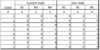
table for 3 bit up counter

present state next state
N A B C
0 0 0 0 0 0 1
1 0 0 1 0 1 0
2 0 1 0 0 1 1
3 0 1 1 1 0 0
4 1 0 0 1 0 1
5 1 0 1 1 1 0
6 1 1 0 1 1 1
7 1 1 1 0 0 0

present state I think present state means this
N A B C
0 0 0 0
1 0 0 1
2 0 1 0
3 0 1 1
4 1 0 0
5 1 0 1
6 1 1 0

next state means

N A B C
1 0 0 1
2 0 1 0
3 0 1 1
4 1 0 0
5 1 0 1
6 1 1 0
7 1 1 1
0 0 0 0


that's circuit is very complex for me don't know any idea what i do next
1)how to find out input for counter
2)how to find out output for counter
 
It's just a counting up in 3 bit binary, the clue is in the name!

your input would be a clock edge, and the binary output will be your current binary plus one!

Of course the counter overflows at 111 and goes to 000.
 
hi vead,
I dont fully understand what you are asking.?

For any simple Binary counter the Next state is simply the Current state +1
so.
Binary '000 '
+1 = 001
+1 = 010
+1= 011
+1=100 .... etc

E
 
hi vead,
I dont fully understand what you are asking.?

For any simple Binary counter the Next state is simply the Current state +1
so.
Binary '000 '
+1 = 001
+1 = 010
+1= 011
+1=100 .... etc

E

I want to implement 3 bit up counter that count 0 to 7 generally I made present state table and then next stable look at my post now I want to make table for counter so confused a lot what is input and output for counter

i think i need k map to minimize the term another question can i do it with finite state machine
 
Last edited by a moderator:
From what I understand your trying to build a 3-bit counter, correct?
why, you can just buy them? In which case I'm guessing this is a school assignment?

Yes of course you can do it with a finite state machine, or a PIC or discreet logic gates or in JAVA. I even think there will be away to do this just using diodes...

So the question is what are you trying to do? Are you trying to build a counter or just understand how one works.
 
hi vead,
I have run a 3 stage binary counter and annotated the waveforms, you should now be able to visualize how it works.
The F/F's change state on the rising edge of the clock inputs
E
 

Attachments

  • AAesp01.gif
    AAesp01.gif
    45.6 KB · Views: 168
Ericgibbs posted while I was writing this, but this just goes to show that you can do this lots of different ways.

I've built my counter out of 1-bit half adders, see attached file. Research '1-bit half adder' on google there is plenty of info.

Now I want YOU to explain to US why these circuits work, you need to put in the hard work yourself to show willing in this subject or I for one won't be offering help in the future.
 

Attachments

  • Capture.JPG
    Capture.JPG
    47 KB · Views: 162
From what I understand your trying to build a 3-bit counter, correct?
why, you can just buy them? In which case I'm guessing this is a school assignment?

Yes of course you can do it with a finite state machine, or a PIC or discreet logic gates or in JAVA. I even think there will be away to do this just using diodes...

So the question is what are you trying to do? Are you trying to build a counter or just understand how one works.

yes you are guessing correct actually I need verilog code for counter so I started to understand basic concept of counter . in verilog we need to define what is input and what is output port but here I am having trouble because there are bunch of inputs and output I couldn't figure out how to define input and output thats why I made post for up counter I am just understanding for verilog code
 
Oh ok, easy.

So you want one input which is your clock. You could use a reset as well but the table for showed at the start doesn't have reset.
You also want an output 'count'.
on clock rising edge you want to add one to your count unless count is at its maximum value.

so something like:

Input clock;
output count;

always @ (posedge clock)
if (count == 3'b111)
count <=3'b000;
else
count <= count + 1'b1;
end

alternatively you can represent my circuit with logic functions
on rising edge;
B0=clk^B0
B1=(clk|B0)^B1
B2=(clk|B0|B1)^B2

You should be able to arrive at my above logic function from study of the logic table or clearly by looking at and understanding my circuit logic adder
 
Last edited:
Status
Not open for further replies.

Latest threads

New Articles From Microcontroller Tips

Back
Top