Continue to Site

Welcome to our site!

Electro Tech is an online community (with over 170,000 members) who enjoy talking about and building electronic circuits, projects and gadgets. To participate you need to register. Registration is free. Click here to register now.

  • Welcome to our site! Electro Tech is an online community (with over 170,000 members) who enjoy talking about and building electronic circuits, projects and gadgets. To participate you need to register. Registration is free. Click here to register now.

Unicorn GLCD demo.

Status
Not open for further replies.
Hello Pommie, it is a great job writing a library like this. Your library is one of the best, most understandable and standard one I have ever come across on the net. Thank you very much for your hard work.


I've just started to learn embedded systems with PIC series. Yesterday I wrote my first "Hello World" application which is actually nothing bot blinking a LED. Now I want to put my effort into something bigger, like interfacing an LCD. I have a few question about your code, but first I want to introduce the relevant information I collected over internet...

Direct links to photos of my LCD (with KS108 controller):
**broken link removed**, **broken link removed**

Port mapping in you code:
Code:
#define GLCD_Data   PORTD
#define b_GLCD_GCS1 LATBbits.LATB4
#define b_GLCD_GCS2 LATCbits.LATC0
#define b_GLCD_RS   LATEbits.LATE0
#define b_GLCD_RW   LATEbits.LATE1
#define b_GLCD_E    LATEbits.LATE2
#define b_GLCD_On   LATAbits.LATA4
#define b_GLCD_BL   LATBbits.LATB3

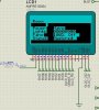
Pin configuration of a KS108 controller LCD:
KS0108 Controller, at the bottom of the page.

Instruction set of the LCD:
**broken link removed**


Now, the point which confuses me is,

Your code defines these 6 connections:
b_GLCD_GCS1
b_GLCD_GCS2
b_GLCD_RS
b_GLCD_RW
b_GLCD_E
b_GLCD_On


LCD has these 6 pins available:
D/I
R/W
E
CS1
CS2
RES


If you try to match these:
b_GLCD_GCS1 == CS1
b_GLCD_GCS2 == CS2
b_GLCD_RS == RES
b_GLCD_RW == R/W
b_GLCD_E == E
b_GLCD_On == ???


One can say that b_GLCD_On should match with D/I, but when you refer to the instruction set of the LCD, D/I pin is for specifying whether our output data at PIC pins is data or instruction. On the other hand, from my understanding (excuse me if I am wrong), b_GLCD_On is used for some other purpose like activating the LCD, I think you control power source of the LCD, by switching on and off a transistor with this pin.

Can you please specify what b_GLCD_On is for, and how you handle D/I pin?
Do you have any sample schematics and code?

Again, thank you for this wonderful project.
I will appreciate if you reply.
 
If you look at his Data and Command code:
Code:
void GLCD_Write_Cmd(unsigned char data){
	Wait_Not_Busy();
	GLCD_Data = data;
	b_GLCD_RS=0;
	b_GLCD_RW=0;
	b_GLCD_E=1;
	Delay();
	b_GLCD_E=0;
}

void GLCD_Write_Data (unsigned char data){
	Wait_Not_Busy();
	GLCD_Data = data;
	b_GLCD_RS=1;
	b_GLCD_RW=0;
	b_GLCD_E=1;
	Delay();
	b_GLCD_E=0;
}

RS is the main item that changes meaning it controls Data or Command hence it has to be D/I
 
Heh i confuse people maybe so here is the code commented to clarify what i mean:
Code:
#define GLCD_Data   PORTD  //DB0 to DB7
#define b_GLCD_GCS1 LATBbits.LATB4  //Chip Select 1
#define b_GLCD_GCS2 LATCbits.LATC0  //Chip Select 2
#define b_GLCD_RS   LATEbits.LATE0  //GLCD D/I
#define b_GLCD_RW   LATEbits.LATE1  //GLCD R/W
#define b_GLCD_E    LATEbits.LATE2  //GLCD E
#define b_GLCD_On   LATAbits.LATA4  //GLCD RES
#define b_GLCD_BL   LATBbits.LATB3  //GLCD Backlight

#define TRIS_Data    TRISD  //TRIS for DB0 to DB7
#define b_TRIS_GCS1  TRISBbits.TRISB4 //GCS1
#define b_TRIS_GCS2  TRISCbits.TRISC0 //GCS2 
#define b_TRIS_RS    TRISEbits.TRISE0 //D/I 
#define b_TRIS_RW    TRISEbits.TRISE1 //RW 
#define b_TRIS_E     TRISEbits.TRISE2 //E 
#define b_TRIS_On    TRISAbits.TRISA4 //RES
#define b_TRIS_BL    TRISBbits.TRISB3 //backlight
 
Last edited:
^ This comments explain everything :)

But now, there is this new term: "RES".
Correct me if I'm wrong,
RS == D/I
RES == RST == Reset
Is that right? :confused:
 
YES heh you got it now

Code:
#define GLCD_Data   PORTD  //DB0 to DB7
#define b_GLCD_GCS1 LATBbits.LATB4  //Chip Select 1
#define b_GLCD_GCS2 LATCbits.LATC0  //Chip Select 2
#define b_GLCD_RS   LATEbits.LATE0  //GLCD RS,D/I
#define b_GLCD_RW   LATEbits.LATE1  //GLCD R/W
#define b_GLCD_E    LATEbits.LATE2  //GLCD E
#define b_GLCD_On   LATAbits.LATA4  //GLCD RES,RST,RESET
#define b_GLCD_BL   LATBbits.LATB3  //GLCD Backlight

#define TRIS_Data    TRISD  //TRIS for DB0 to DB7
#define b_TRIS_GCS1  TRISBbits.TRISB4 //GCS1
#define b_TRIS_GCS2  TRISCbits.TRISC0 //GCS2 
#define b_TRIS_RS    TRISEbits.TRISE0 //RS, D/I
#define b_TRIS_RW    TRISEbits.TRISE1 //RW 
#define b_TRIS_E     TRISEbits.TRISE2 //E 
#define b_TRIS_On    TRISAbits.TRISA4 //RES,RST,RESET
#define b_TRIS_BL    TRISBbits.TRISB3 //backlight
 
Last edited:
Doesn't work... :(

Below are the pieces of code which I modified or appended:

glcd.h
Code:
#include <p18f2550.h>

#define GLCD_Data   PORTB
#define b_GLCD_GCS1 LATCbits.LATC7
#define b_GLCD_GCS2 LATCbits.LATC6
#define b_GLCD_RS   LATCbits.LATC0
#define b_GLCD_RW   LATCbits.LATC1
#define b_GLCD_E    LATAbits.LATA5
#define b_GLCD_On   LATCbits.LATC2
#define b_GLCD_BL   LATAbits.LATA4	// Not used in my project

#define TRIS_Data    TRISB
#define b_TRIS_GCS1  TRISCbits.TRISC7 //GCS1
#define b_TRIS_GCS2  TRISCbits.TRISC6 //GCS2 
#define b_TRIS_RS    TRISCbits.TRISC0 //RS 
#define b_TRIS_RW    TRISCbits.TRISC1 //RW 
#define b_TRIS_E     TRISAbits.TRISA5 //E 
#define b_TRIS_On    TRISCbits.TRISC2 //RST
#define b_TRIS_BL    TRISAbits.TRISA4 //backlight

glcd.c
Code:
void Delay(void){
	_asm	NOP	_endasm
	_asm	NOP	_endasm
	_asm	NOP	_endasm
	_asm	NOP	_endasm
	_asm	NOP	_endasm
	_asm	NOP	_endasm
	_asm	NOP	_endasm
	_asm	NOP	_endasm
	_asm	NOP	_endasm
	_asm	NOP	_endasm
}
(Tried single NOP, five NOPs, and this 10-NOPed one, non worked.
I didn't change any other function in this file (Except for replacing "#include <p18f4550.h>" with "#include <p18f2550.h>").)


main.c
Code:
#include <p18f2550.h>
#include "glcd.h"
#pragma config WDT	= OFF
#pragma config MCLRE	= ON
#pragma config DEBUG	= OFF
#pragma config LVP	= OFF
#pragma config PLLDIV	= 5		// need 5 for 20MHz xtal
#pragma config CPUDIV	= OSC1_PLL2	// CPU Clock = 96 MHz/2 = 48 MHz
#pragma config USBDIV	= 2		// 96MHz PLL/2 = 48 MHz for USB clock 
#pragma config FOSC	= HSPLL_HS	// High Speed Crystal / Resonator with PLL enabled

void main (void)
{
	while (1)	// Nothing changes if I remove this infinite loop
	{
		Init_GLCD();
		
		PutMessage((rom char*)"\x16\x24\x08 Blueroom\x16\x20\x10 Electronics\n Title:\n Author:\n Date:\n Hardware:");
		PutMessage((rom char*)"\x16\x38\x18Graphic demo.");
		PutMessage((rom char*)"\x16\x38\x20Mike Webb.");
		PutMessage((rom char*)"\x16\x38\x28June 20 2007.");
		PutMessage((rom char*)"\x16\x38\x30Unicorn.");
		
		box(1,1,126,62);
	}
	
	while (1);
	
	// Working "Hello World" example
	/*unsigned char i, j;
	TRISB = 0;
	while (1)
	{
		PORTB = 0x00;
		Delay1KTCYx(i);
		PORTB = 0xFF;
		Delay1KTCYx(255-i);
	}*/
}

Below are the photos of my circuit:
**broken link removed**, **broken link removed**

I checked signal levels at PIC pins with an oscilloscope and everything looks alright. OSC1 and OSC2 has clock pulses; data port, and other relevant LCD pins have meaningful pulses. I think it is likely that there has to be mistake in my code.

And, I found a new datasheet (uploaded as an attachment) for my LCD, and after reading it I realized that the pin configurations in my first post in this thread was wrong. I rebuilt the circuit by refering to this new datasheet; yet it still isn't working...

I'm totally stuck!
 

Attachments

  • CFAG12864BWGHV.pdf
    1.5 MB · Views: 1,296
Last edited:
Move the init out the while loop first of all I'll take a look at it closer in a minute
Did so, but it is still the same. The screen is blank. Back-light is on, and I can adjust the contrast, but nothing else.


...can u post a schematic for me just for fun
Unfortunately I didn't use any schematics, actually I couldn't find any schematics. I built up the circuit on a bread-board (the one you see in the link in my previous message) just by looking at PIC and LCD datasheet.
 
Need more information...

I read some datasheet about "xG12864x-xxx-x" LCD unit. I realized a point, pin configuration differs for every product. Even if the you manage to catch the rightful pin locations and match them perfectly between PIC and LCD, you system could not work because some pins may be complemented on the LCD side.

For example,
In "Crystalfontz America" model (CFAG12864B-WGH-V) CS1 and CS2 bits are complemented, while in "Winstar" model (WG12864B) CS1 and CS2 bits are not complemented.
This was just an example, there are more that CSx bits that differ. For example E (Enable) is complemented in some LCDs, and not complemented in others.

I really need a detailed pin configuration from one of you who succeeded in this project.
I need to know:
  1. Your LCD model (pin configuration, and which bits are complemented on the LCD side)
  2. If you made any modifications in the original code Pommie gave

************

YES heh you got it now

Code:
#define GLCD_Data   PORTD  //DB0 to DB7
#define b_GLCD_GCS1 LATBbits.LATB4  //Chip Select 1
#define b_GLCD_GCS2 LATCbits.LATC0  //Chip Select 2
#define b_GLCD_RS   LATEbits.LATE0  //GLCD RS,D/I
#define b_GLCD_RW   LATEbits.LATE1  //GLCD R/W
#define b_GLCD_E    LATEbits.LATE2  //GLCD E
#define b_GLCD_On   LATAbits.LATA4  //GLCD RES,RST,RESET
#define b_GLCD_BL   LATBbits.LATB3  //GLCD Backlight

#define TRIS_Data    TRISD  //TRIS for DB0 to DB7
#define b_TRIS_GCS1  TRISBbits.TRISB4 //GCS1
#define b_TRIS_GCS2  TRISCbits.TRISC0 //GCS2 
#define b_TRIS_RS    TRISEbits.TRISE0 //RS, D/I
#define b_TRIS_RW    TRISEbits.TRISE1 //RW 
#define b_TRIS_E     TRISEbits.TRISE2 //E 
#define b_TRIS_On    TRISAbits.TRISA4 //RES,RST,RESET
#define b_TRIS_BL    TRISBbits.TRISB3 //backlight

Can you please specify which of these bits were complemented in your implementation, and what model LCD did you use?

This would help greatly if you answer this question.
 

Attachments

  • WG12864A.pdf
    275.6 KB · Views: 331
  • WG12864B.pdf
    463.1 KB · Views: 769
Is there a way to invert the colors of display (black font with blue or green background) ?

Yes, you need to add the bits in red,
Code:
void GLCD_Write_Data (unsigned char data){
	Wait_Not_Busy();
	GLCD_Data = data[COLOR="red"]^0xff[/COLOR];
	b_GLCD_RS=1;
	b_GLCD_RW=0;
	b_GLCD_E=1;
	Delay();
	b_GLCD_E=0;
}

unsigned char GLCD_Read_Data(void){
	Wait_Not_Busy();
	TRIS_Data=0xff;
	b_GLCD_RS=1;
	b_GLCD_RW=1;
	b_GLCD_E=1;
	Delay();
	W=GLCD_Data[COLOR="Red"]^0xff[/COLOR];
	b_GLCD_E=0;
	TRIS_Data=0x00;
	return W;
}

Mike.
 
Thank you Pommie for the quick reply, it has inverted the Data but now there is a new problem.

The backgound is still black and the text is inverter (Black font with blue background) what i wanted. However i actually wanted to make the complete background blue and only font black..

The attached image will help you understand what i meant.

The text is displaying okay but the background is annoying now :(

I have solved this issue but the method is really stupid so i was looking for a more professional solution for it :p
 

Attachments

  • Untitled.jpg
    Untitled.jpg
    86 KB · Views: 369
Status
Not open for further replies.

Latest threads

New Articles From Microcontroller Tips

Back
Top