Woot! my first post...
So here is the situation...
I'm doing some experimenting with ultrasonic vibration, using a 100w welding transducer and later, when my cnc mill arrives, some custom made transducers (designed with FEA)...
I'd like to keep the costs reletively low ... so I've opted for doing the electronics myself... I have a bit of experience with electronics but not in the area of power amplifiers..
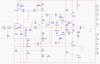
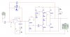
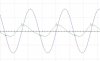
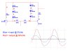
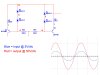
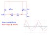
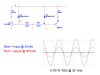
I came across a schematic in a pdf file about ultrasonics... It seems a bit old since some of the components are obsolete... I modeled the schematic, had to swap a few parts and simulated it... It runs alright when fed a 20kHz signal, but responds poorly outside of this range...
I need to run it with a sine wave as I hope to achieve standing waves of a particular frequency, square wave would give me too many harmonics ...
I will build a sine wave generator later for testing and finally a PIC to generate the signal.... input should be from 0 to 1 volt.
So... to summarize things... these are my basic requirements
Power: >150watts (more is better)
Frequency responce: 18kHz to 30kHz
Amp type: push/pull Type B or AB
And about the circuit...
D2 and D4 are supposed to be BZV46/1.5V Reglator reference diodes
I changed them to 2.2V zeners (and turned them around) since I could find that part... I couldn't get it to simulate with a similar diode
R1 and R9 are adjusted to better match the 2 zeners, they were 680 ohm and 91 ohm originally...
Q12 was a BUZ34, now its a IRF240
Q10 was a RFM10P15, now its a IRF9240
Output step up transformer is not shown, it would be about a 1:3
Please comment on what I've done wrong... I need some serious advice here...
Thanks a bunch!
Michael Grant
So here is the situation...
I'm doing some experimenting with ultrasonic vibration, using a 100w welding transducer and later, when my cnc mill arrives, some custom made transducers (designed with FEA)...
I'd like to keep the costs reletively low ... so I've opted for doing the electronics myself... I have a bit of experience with electronics but not in the area of power amplifiers..
I came across a schematic in a pdf file about ultrasonics... It seems a bit old since some of the components are obsolete... I modeled the schematic, had to swap a few parts and simulated it... It runs alright when fed a 20kHz signal, but responds poorly outside of this range...
I need to run it with a sine wave as I hope to achieve standing waves of a particular frequency, square wave would give me too many harmonics ...
I will build a sine wave generator later for testing and finally a PIC to generate the signal.... input should be from 0 to 1 volt.
So... to summarize things... these are my basic requirements
Power: >150watts (more is better)
Frequency responce: 18kHz to 30kHz
Amp type: push/pull Type B or AB
And about the circuit...
D2 and D4 are supposed to be BZV46/1.5V Reglator reference diodes
I changed them to 2.2V zeners (and turned them around) since I could find that part... I couldn't get it to simulate with a similar diode
R1 and R9 are adjusted to better match the 2 zeners, they were 680 ohm and 91 ohm originally...
Q12 was a BUZ34, now its a IRF240
Q10 was a RFM10P15, now its a IRF9240
Output step up transformer is not shown, it would be about a 1:3
Please comment on what I've done wrong... I need some serious advice here...
Thanks a bunch!
Michael Grant