I made a mistake, sorry.Hi J and M,
Here is the latest program:
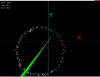
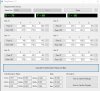
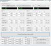
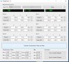
360 CW + CNTL1 shows:
BYTES = 3x Outputs after twos compliment calc inside [ ], then the CNTL1 BYTE=18 shows the compass is in CONTINUOUS MODE and 16BIT.
DATA = 6x RAW BYTEs
All from a Terminal while rotating 360 CW.
C.
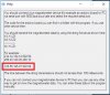
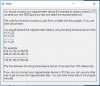
I was looking about taking absolute value of 16bit word in 2's complement
In the conversions there should be:
Xsing = Xsing - 65536 instead of 65536 - Xsing
Ysing = Ysing - 65536
Zsing = Zsing - 65536
Now the first row becomes: - 89, 51, - 238
the last: - 71, 55, - 97
Last edited:
")