Continue to Site

Welcome to our site!

Electro Tech is an online community (with over 170,000 members) who enjoy talking about and building electronic circuits, projects and gadgets. To participate you need to register. Registration is free. Click here to register now.

  • Welcome to our site! Electro Tech is an online community (with over 170,000 members) who enjoy talking about and building electronic circuits, projects and gadgets. To participate you need to register. Registration is free. Click here to register now.

TV Set 'Fails' Now and Then

Status
Not open for further replies.
Hi again,

Yes, the kind used for PC computers, +12, +5, etc., outputs.
The symptom was the PC would keep turning off for no apparent reason.
 
Hi again,

I have some new information to add to the problem.

When the tv sits off or in standby, when i go to turn it back on later it tries to light up the screen to show the logo, but then it goes dark.
I didnt notice this before because i was farther from the TV, but yesterday i had it off for about an hour while i went out for some things, and when i came back it would not turn on even after several tries this time (turn off, then back on), so i examined it a little better.
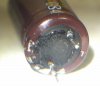
It looks like it tries to start the tube, but then detects a problem of some sort and turns off. I could guess this could be a momentary higher than normal voltage due to bad caps but it's hard to say right now. Like Nigel said it could very well be the tubes going, as i have seen other tubes from regular home lamps go too and almost the same thing happens, they try to turn on but cant. But this one turns off completely after only one try. I have read now that some other sets try repeatedly, after some time interval. Perhaps this one does try again but after some time has passed, so i'll have to see.

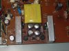
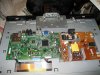
I have also seen a web site now where they took one apart (not the exact model though), and it looks pretty straightforward. Take the back screws out, and the main power supply and board should be exposed for examination.

I looked and looked for a tv out on the web but didnt find anything i really liked that much. Most of the Sony's being sold are 32 inch and i dont really want that big. I found a cheap one but the only model left in the store is the demo model, and they dont come down on the price for demo models! So it looks like i'll be taking a look at this thing very soon. Have other things going too though that take precedence so not sure when i'll do this, but it should be interesting as it will be my first LCD tv.

BTW the only way i got it to start this time was to give the back a couple of sharp smacks, then turned it on and it started up!
So the Caveman method works again :)
 
Most of the Sony's being sold are 32 inch and i dont really want that big.

A 32 is really a pretty small TV these days, and with the modern tiny surround it's barely bigger than the LCD screen itself.

I've got a 42 in the living room, and 32's in the bedrooms - I wouldn't want anything smaller, even for a bedroom set.
 
BTW the only way i got it to start this time was to give the back a couple of sharp smacks, then turned it on and it started up!
So the Caveman method works again :)

That's a good sign of a bad solder joint somewhere.
 
Hi,

Yeah maybe it's as simple as that, but then again that could be hard to find.

The other thing that was strange was that often when i pressed the 'volume' button on the TV itself the input source would change, which was a pain because then i'd have to reset that too. That could be the cold solder joints too.

It probably wont be long now before i dig into this a little more, but i have other more pressing things to attend to at the moment.
At the very least i intend to take some close up pics of the inside, assuming it comes apart.
 
Hi again Nigel,

Thanks for the info again, and so with that info it looks like i will have to try this then. I dont like the TV that much anyway so if it screws up, i'll use it for parts :)

I didnt really feel like buying another one right away though, that's what really bites, so maybe repairing will work out. It will be interesting for me in any case.
 
Hello again,

Ok i managed to get it apart, not as easy as it sounds as there were many screws and other stuff to remove in order to get to the power supply. Here are some pics, and it looks pretty clear that three out of the four electrolytics in the pics are bulging at the top. I also included a shot of the whole circuit board. So it definitely looks like some caps are bad, in the low voltage section (16v ratings on all four caps). I doubt i have any that small though laying around.

BTW how long should we wait before working on the circuit board, for the voltages to die down?
Also, what would be the max voltage for the light tube driver, like 300v or something like that or a little lower?

Thanks :)
 

Attachments

  • AOC_TV-01.jpg
    AOC_TV-01.jpg
    245.9 KB · Views: 303
  • AOC_TV-02.jpg
    AOC_TV-02.jpg
    192.9 KB · Views: 292
  • AOC_TV-03.jpg
    AOC_TV-03.jpg
    137.6 KB · Views: 304
  • AOC_TV-04.jpg
    AOC_TV-04.jpg
    161.5 KB · Views: 305
BTW how long should we wait before working on the circuit board, for the voltages to die down?
Also, what would be the max voltage for the light tube driver, like 300v or something like that or a little lower?

Make sure they are discharged by connecting a resistor across them, or more likely a screwdriver :D

The input to the inverter is low voltage, often 24V or so - the output though is in the thousands, and not something you ever need to measure.
 
Hi Nigel,

Oh wow i didnt realize the tubes would need that high of a voltage, thanks for telling me. I thought it would be lower because i had been able to run regular fluorescent tubes at much lower voltage like 120v way back when.

Anyway, i managed to get the power supply board flipped over. I could not remove it entirely because four of the connectors on one side would not come loose and i didnt want to break them trying to get them disconnected. So folding the board over i was able to unsolder two of the caps. I only had one 1000uf 16v cap on hand and although the other cap i chose to remove was 1500uf 16v i only had a 2200uf 16v on hand so i used that. But after removing the two caps that had the worst bulge, i noticed that the 1500uf cap had some black gook under it (cap C824). Sure enough, that one had leaked extensively (see photo).

So i got two of the four caps replaced, and fired up the set, and guess what, it turned on immediately. Before that it would not turn on again at all yesterday even after 10 to 20 tries, and now it turned on with the first try, so i figure that was the whole problem as many here had suspected. I now only have to get one more cap to finish the repair.

Thanks to everyone here who added ideas and suggestions, especially you Nigel.

I am posting the pic with the black gook showing on the circuit board after two caps had been removed. I wanted to add that although this is clearly visible now, it was not visible before removing the cap because the caps were mounted very close together so you could not see the surface of the PC board itself, just the caps. So the gook came out the bottom, not the top as i have seen before, so it was a little harder to tell which cap was the worst. I had to judge by the one that looked like it had the highest bulge on top :)

You can also see a slight bulge in the other cap on the right that i did not get to change yet because i have to purchase another cap first. But the set is up and running fine now even so.
 

Attachments

  • AOC_TV-05.jpg
    AOC_TV-05.jpg
    181.3 KB · Views: 292
Oh wow i didnt realize the tubes would need that high of a voltage, thanks for telling me. I thought it would be lower because i had been able to run regular fluorescent tubes at much lower voltage like 120v way back when.

As I mentioned earlier, they aren't fluorescent tubes, they are CCFL's :D
 
Hi again,

Yes thanks, i havent done much with them in the past, mainly just the fluorescent type.
 
Hello again,

I took a look at some spec's and they are stating over 800 volts. That's pretty high. Funny though this power supply doesnt look like it goes that high, just by looking at the construction. It looks more typical. I wonder if they might be using regular fluorescent. I'll look into this more when the new caps get here.

Here's a close up of the worst cap of the bunch, showing the bottom how bad it leaked. Looks really nasty.
It is a Kemet brand, but the only other marking is "0841". I am guessing that is the 41st week of 2008, but that does not help me find the series name identification. The only other info is the value 1000uf and 1500uf and the voltage rating of 16v on both caps, and there is also "LS" which has something to do with the environmental element content. Nothing else though.

The second pic shows how the cap feels about the whole ordeal :)
 

Attachments

  • BadCaps6b.jpg
    BadCaps6b.jpg
    133.1 KB · Views: 316
  • CapBlowingItsLid.jpg
    CapBlowingItsLid.jpg
    49.5 KB · Views: 328
Last edited:
Hello again,

I took a look at some spec's and they are stating over 800 volts. That's pretty high. Funny though this power supply doesnt look like it goes that high, just by looking at the construction. It looks more typical. I wonder if they might be using regular fluorescent.

No, as I've said CCFL's only, normal tubes aren't suitable, and would be far too large.

There's often some little blue high voltage capacitors in the bottom end of the tubes, those are rated 2KV (or more).

Normal tubes strike at a low voltage because they are heated, you can make them strike without heating by applying a MUCH higher voltage to them, just like a CCFL.

Generally the voltage is reduced once the tube has struck (you get curves of the required shape in the datasheets), and is presumably reduced further to control brightness.
 
Hi again,

Ok, well i'll take a better look very soon, the capacitators just got here a today, a little while ago, so i'll be finishing up the job soon i hope. I will have then replaced all four of them in that power supply section.

Thanks again for all the info Nigel :)
 
Hi Nigel,

Well that's interesting because i often buy Panasonic caps! They seem to be reasonably priced. I always get 10000 hrs @ 105C or better too. This time i got Rubycon, but mainly because i got a good quantity discount. I was a little disappointed this time though in that they shipped with SHORT leads, something i have rarely seen in a brand new capacitor. The leads are only about 0.375 inches long and are BOTH the same length. Normally they are at least an inch long, one slightly longer to indicate polarity. Luckily i only need these to mount into circuit boards which require only about 0.25 inch lead length.

When i get this thing apart (over the weekend) i'll check for the small capacitors on the tubes. I hope i can get into that part of the construction without removing anything else though, but it looks like they have that part enclosed so no light comes out the back of the TV through the air vent slots.

The strange thing is the only other capacitor that looks like it is part of a power supply is this bigger electrolytic, and it does not look like it could be a 1000v rated capacitor. It's hard to tell though because they have it mounted with the value pointing down and they have glue all over it so i can not move it at all to check. Take a look at the pic again and see what you think.
The power supply section is on the right, the brown PC board.

I see now that the designer of the PC board for the power supply did not take into account the physical position of those four caps relative to the yellow transformer. The yellow transformer (as any) would get hot, and the heat would rise, and because the four caps are mounted right ABOVE the transformer when the TV is standing in the normal viewing position, the caps get literally cooked by the transformer, especially the ones closest to the transformer. Had they mounted the transformer above the caps instead, these caps would probably have not blown out yet. There's no fan, so the heat generated from any component follows a natural coarse of rising up, and anything above it gets heated not only from it's own internally generated heat but also because of the thing below it. It's so close in proximity too, so that's very bad.
I will be adding a heat shield as well.
 

Attachments

  • AOC_TV_Inside-01.jpg
    AOC_TV_Inside-01.jpg
    245.9 KB · Views: 289
Last edited:
The strange thing is the only other capacitor that looks like it is part of a power supply is this bigger electrolytic, and it does not look like it could be a 1000v rated capacitor.

It's the reservoir capacitor, should be rated at 350-400V or so for UK mains, could be half that for only 110V mains.
 
Hi again,

Ok, so i guess that is similar to the two we usually see in the PC power supplies then? They work with the mains and supply power to the main transformer which then creates the lower voltages.

I guess what else i am saying is that i have not yet identified the high voltage section, and by that i mean the 800v section or whatever it is.

I guess what i will do next is replace the caps, and while i do that i'll take a pic of the bottom of the board. I dont know how i forgot to do that previously, i guess i was in a hurry to see if changing the two worst caps would actually make a difference so i hurried up and put it back together and tested it before it thought about tracing out the circuit any more. No other caps looked bad, so i didnt worry about it too much. But now that i've gotten this far with it, i might as well study it a little more, since i'll have to take it apart again anyway for the final repair.

But one other little question, how long do you think it is recommended to wait before working on the set again? What i think you said before was to discharge the caps, but i dont think i can get to all the caps especially the very high voltage ones because that in turn requires more disassembly which in turn means of course handling the two boards, and handling the two boards is what i am worried about in the first place. I would not think that it should take too long, but i remember the old CRT's that would hold the charge for quite some time. Maybe the modern circuits are better now?
 
Hi again,

Ok, so i guess that is similar to the two we usually see in the PC power supplies then? They work with the mains and supply power to the main transformer which then creates the lower voltages.

I guess what else i am saying is that i have not yet identified the high voltage section, and by that i mean the 800v section or whatever it is.

It's the square transformer at the middle of the far right of the picture, the blue capacitors to the right of that are the 2KV ones, and the four little white plugs are the feed to the CCFL's. The drivers and IC for it are probably SM under the board.

Here's a bit about inverters on Wikipedia:

https://en.wikipedia.org/wiki/CCFL_inverter

But one other little question, how long do you think it is recommended to wait before working on the set again? What i think you said before was to discharge the caps, but i dont think i can get to all the caps especially the very high voltage ones because that in turn requires more disassembly which in turn means of course handling the two boards, and handling the two boards is what i am worried about in the first place. I would not think that it should take too long, but i remember the old CRT's that would hold the charge for quite some time. Maybe the modern circuits are better now?

The only thing to retain any dangerous voltage is the afore mentioned reservoir capacitor, simply shorting it with a screwdriver will ensure it's discharged :D
 
Status
Not open for further replies.

Latest threads

Back
Top