Continue to Site

Welcome to our site!

Electro Tech is an online community (with over 170,000 members) who enjoy talking about and building electronic circuits, projects and gadgets. To participate you need to register. Registration is free. Click here to register now.

  • Welcome to our site! Electro Tech is an online community (with over 170,000 members) who enjoy talking about and building electronic circuits, projects and gadgets. To participate you need to register. Registration is free. Click here to register now.

TV-out circuits on VGA card failing...

Status
Not open for further replies.

MrGnome

New Member
Hi!

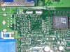
A while ago the voltages from my TV-out (Composite) on my ATI Radeon 9800 card dropped, with the result being a very dark and grey picture. Tops measured with a scope are about 250mV with white output, and they should be about 1000mV. This happened after connecting to the TV while the TV was on. The circuit on the card has both composite and S-vhs output on a 7-pin "enhanced" s-vhs socket. (the extra pins are for the composite signal)

First the composite signal went dark, but the s-vhs signal was ok, so i got a cheap converter cable that worked quite ok for a while, until i forgot to turn off the TV when i connected the cable one night, and the same thing happened to the svhs circuit. The luminance range was "squashed"

I don't have schematics for the TV-out circuitry on the card, but the contrast and saturation settings in my driver works a little bit, so the circuits handling the changes seem ok.

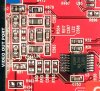
I don't know how these composite converter circuits work, but i guess some component has died, "zapped" by a strange grounding problem or similar on the tv.

Perhaps it would be possible to change a failing component on the card, if i just know which one it is.

(Attached is the signal viewed in PICO Scope, showing the levels. signal source is a white screen)

Please, if you have any information, give me a hint or two :(
 

Attachments

  • composite.GIF
    composite.GIF
    51 KB · Views: 1,372
Well, I am going to take a stab at it since no one else is.

First take a look at your video card, and very near the composite or SVideo output connectors you should find R, and C's and diodes. These are generally for ESD protection (and sometimes for EMI filtering as well if you see some L's in there too). The diodes in particular clamp the output (2 diodes per line) so that the signsl cannot go one diode drop above VCC, or one diode drop below ground). You need to probe around to find out which one got zapped.

Also, looking at your signal, it appears that both the sync tips and peak video are about 1/3 their nominal levels. May be you could add a simple X3 gain video amp to bring the levels back up to normal. Won't repair your video card, but will mask the problem.

Hope this helps,

Jem
 
Thanx a lot! I'm gonna try to check the board for failing circuitry, problem is everything is so darn tiny ;). Thanx also for your suggestuion for a 3X video amp. Are they hard to build? Would that give me a clear picture?
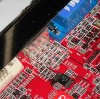
I'm quite new to video electronics so I'm a bit confused as to how a video amp works.

Again, thanx a bunch for Your help, if you could give me more hints on how to build an Amp, or where i can find one, that'd be great. I guess that would be the easiest solution. I'm a bit worried about soldering on my $300 video card... :wink:

Got some pics here, this is what it looks like just beside the video out port, it's probably one of these buggers then. Got some L's as You can see L20 L21 and L22. Problem is i don't know what values they should have. How do i know if one is zapped? Sorry for being such a newbie:
 

Attachments

  • perspective.jpg
    perspective.jpg
    53.2 KB · Views: 1,290
  • top.jpg
    top.jpg
    30.8 KB · Views: 1,295
Okay, yes I guess it's the easiest way to get things fixed up. Got to consult some of my more electro-kompetent friends for this one I'd say. I also hope i can find that amp somewhere else, because shipping it to me in Scandinavia would cost me $25 :wink:

Still feel a bit tempted to just replace one or two of those small components, I've soldered that type of tiny R's before, and know it's tricky business, but not impossible.... if i just could find out which one is faulty....

Well, anyway, thanx for all Your help Jem!

EDIT:

Actually I found I had an LM324 amp (4x1 amps), so I'm planning on making something like the pic below. Using Multisim 2001 I simulated this circuit, and it amplifies 300mV to about 900mV, so I should be quite close with that. However multisim achieves this level without any current sent to the LM324. Is this possible? Will the loopback still amplify without an external power source for the LM324?

Please tell me if something looks very wrong with my plans :wink:
 

Attachments

  • videoamp.GIF
    videoamp.GIF
    7.1 KB · Views: 1,273
At it again

Hello!


Planned to make this amp now, but I'm going to need some more help. Where does a current feedback OP-AMP get its power from? do i need a transformer of some sort?

Also the link to the op-amp given above is dead now, so any more hints on how to build this thingy would be great!

:)

btw, if someone thinks I still have a chance of fixing it just by replacing some of the components pctured above, i have some more info. The card thinks a TV is connected, ie it feels some sort of resistance on the socket, thinking it's plugged. I don't know how low this resistance must be for it to "feel" the tv, but this must mean that a resistor has a value too low somewhere just after the connector. right? Would removing some of the resistors completely just for testing be dangerous?

I just wish there was a way to find out their values....
 
I don't think the problem is in that area, I don't know much about ATI cards, but I can almost say that the problem is in the UUT and or in combination to the GPU or other circuit drivers.
 
Okay, but could You please tell me what the UUT is?

The card HAS worked fine until i plugged it in uncarefully and touched tv earth with the cards tv-out cable signal pin. I have tried different driver versions and tried the card in another computer with the same result.

I appreciate Your oppinion, bur I don't think this is a driver issue, I suspect a shorted resistor on the output "line" just before the tv-out connector.
 
I was talking about circuit drivers not software drivers.

The U is a driver IC that delivers the NTSC or PAL format to your TV, if the U is degraded or damaged the signal produced gradually goes to nothing over time, since this is a multi-stage layer formatting for a PC monitor the layer extraction is minimal, but the drivers are somewhat complex as several can fail and still get a deminished signal from the U.

Usually abrev'ed U# and come in all kind of sizes, are extremely sensitive to ESD and are extensivly isolated. If those L comonents are bad they are bad, usually if one is bad the circuit fails to deliver anything, and the components are usually there for protection.

Since this card has circuitry for TV out, but not installed, you can easily see where the U goes. And the U just below it is not required either as this delivers or conditions the format to the top U.

Certain memory are considered U as well. Well most IC's are considered U's

'L' usually stands for inductor usually not marked.
'C' capacitor sometimes marked
'R' Resistor and are ussually marked value
'D' Diode, Diode transistor
'Q' Transistor or amp of some sort, dropout regulators
I used the Term UUT wrong it means nothing to the actually meaning of a IC placed on a PCB U###, I think it just means Integrated Circuit.
 

Attachments

  • p1010300sm.jpg
    p1010300sm.jpg
    302.1 KB · Views: 955
Thank You very much for this explanation, however since i'm not really in to these things I didn't quite understand what You were trying to say, even though I read it 5 times :). (Not a native english-speaker either, perhaps that makes it harder)

Edit: Well now i read it a few times more, and understand a bit more.

Is this correctly understood:

As I can see in Your picture, the Video output IC, or U, is connected first via some C's L's and R's, then it is connected to the TV-out Port. The C's L's and R's are for protection of the IC. If one of these components fail, the circuitry (IC+C's L's and R's) does not provide a good signal.

The card was probably damaged due to some kind of small surge from the TV as i connected the cable. This probably has damaged some of the protection components, and the IC might still be ok.

If i find the faulty L, C or R i should be able to replace it and get the circuitry working again. This, if not the IC itself has failed. If this is the case, how do i find out the values for the protection components? I have tried to mail HIS for schematics or more info, but the seem reluctant to help me.

Again, thanx a lot Juglenaut!
 
since this is a multi-stage layer formatting for a PC monitor the layer extraction is minimal, but the drivers are somewhat complex as several can fail and still get a deminished signal from the U.
Juglenaut, what does this mean? What is multi-stage layer formatting? What do you mean by "layer extraction is minimal"?
 
How do you think graphics are made??

As I said it Layer extraction required to run in NTSC or PAL is minimal compared to full format you see on the monitor. There are a number of different layers to a given scheme of objects, especially since the images are emulated through software, compiled, transfered, driven, and then rendered. Even if you play A DVD it still goes though this process. Although most graphics integrated in a compile and ran at the same time different aspects of certain graphics have to be rendered separatly, but syncronous.

Only on the best Video cards you will see great motion pictures, fixed pictures, textures, and such through your VGA TV out connection on a card, even then you must have a TV that can render the image fully.

You can try and replace all the SMT, but I really don't think the problem lies there in the components.
 
Juglenaut said:
How do you think graphics are made??

As I said it Layer extraction required to run in NTSC or PAL is minimal compared to full format you see on the monitor. There are a number of different layers to a given scheme of objects, especially since the images are emulated through software, compiled, transfered, driven, and then rendered. Even if you play A DVD it still goes though this process. Although most graphics integrated in a compile and ran at the same time different aspects of certain graphics have to be rendered separatly, but syncronous.

Only on the best Video cards you will see great motion pictures, fixed pictures, textures, and such through your VGA TV out connection on a card, even then you must have a TV that can render the image fully.

You can try and replace all the SMT, but I really don't think the problem lies there in the components.
Well, I gave no thought to how graphics are made, because I doubt that it is relevant in this case.
I imagine that RGB are combined in a resistance summing network to form the luminance signal:
Gray = 0.30 * red + 0.59 * green + 0.11 * blue
and the 3.58 MHz color subcarrier is modulated by R-Y and B-Y, or I and Q, or whatever chroma scheme is chosen, then the resulting modulated subcarrier is combined with luminance and the result amplified and sent to the composite video output terminal.
Do you know for a fact that it is done otherwise?
 
Status
Not open for further replies.

New Articles From Microcontroller Tips

Back
Top