Continue to Site

Welcome to our site!

Electro Tech is an online community (with over 170,000 members) who enjoy talking about and building electronic circuits, projects and gadgets. To participate you need to register. Registration is free. Click here to register now.

  • Welcome to our site! Electro Tech is an online community (with over 170,000 members) who enjoy talking about and building electronic circuits, projects and gadgets. To participate you need to register. Registration is free. Click here to register now.

Turn on and off air valves

Status
Not open for further replies.

thup

New Member
Hello, I'm new to the forum. I've been looking around and there seems to be a lot of great info here!

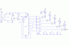
Maybe you guys can help me out with a project. I am trying to construct a simple circuit to turn on and off 5 air valves in the sequence:
Valve # 1 turn on for 2 sec. then turn off 8 sec. after valve #1 turn off valve # 2 turn on for 2 sec. then turn off 8 sec. after vave # 2 turn off valve # 3 turn on for 2 sec. and so on.
This cycle repeat untill the main switch cuts off the power (12 volts)
Thank you for your help
 
turn on some air valves

It shouldn't be to difficult. The key question is how much current do the
valves draw? I think they are probably selenoid type valves. If you don't know how much current they draw, knowing the resistance of the coils we can calculate the current draw. The design of the timing would consist of two timers and a counter and some misc.
gating circuits. I would be happy to draw a complete circuit when I know
the current requirements of the valves.
:lol: Ned
 
Hello Ned,
Thank you for your help and here are the info.
Rated current : 462mA
Coil resistance : 25 Ohms +/- 10%
Power comsumption : 5.54W
Max duty cycle : 20%
Thank you
Thup
 
Why try to build what you can buy cheap enough. Carl's Electronics https://www.ElectronicKits.com has a nice pre-built 8-relay board that runs directly off parallel port. Assembled price is US$29.95 + shipping. Some simple Basic programming and you are off and running.
Carl's Item # is CK1601A. Relay provides NO/NC contact set rated at 12 amps but recommends no more than 7 amps continuous. Requires +12VDC for the circuit card (12 volt relay coils).
Dialtone
 
Controlling air valves

Dialtone is correct, the kit will do the job if you want to control the valves from a computer. Let me know if you want to go that route.
:D Ned
 
Thank you for your idea Dialtone! But I cannot carry my project and the PC around so I still need help from Ned. I will try to use this kit for something else later for my home. One more thing Ned! From your circuit how ease to change the duration of on-off cycle for each valve?
Thup
 
Turning on air valves

Thup
Need some more information:
Is the total # of valves 3? if more than 3 tell me the total # of valves.
I can make the on times variable, but how accurate do you need the
times?
Ned
 
thup,

Have a look at binary ripple counters, 4020, 4060 etc. You make one clock, can even be an xtal, this will in turn give you many clock cycles back, 2 sec, 8 sec, 4 hours. Take whatever output you want, say one at 10 sec and another at 2 sec into a couple of AND gates and you have an output for 2 seconds every 8 sec.
 
If you don't need precise timing, this should work. I haven't tested it. You can tweak the pulse widths by making changes to R6, R7, and C1. You can pick another MOSFET. It should have Rds less than 1 ohm, and be able to tolerate 12 volts gate-to-source.
 

Attachments

  • air_valve_driver.GIF
    air_valve_driver.GIF
    15.5 KB · Views: 944
air valve driver

The attached schematic should do the job. The NE555 generates a precision 1 second clock pulse. It drives the 4017 which divides the time to 10 seconds. U3 a,b,c, is connected in a OR gate configuration to OR the 0 and 1 outputs to generate a gate 2 seconds wide. The 2N3904 transistor is a LED driver. The 1M pot in the 555 circuit is adjusted so the the time between the LED coming on is 10 seconds. U4 generates two positive triggers one on the rising edge of the the 2 second gate and one on the faling edge. This triggers the second 4017 counter. The outputs are taken from the 0,2,4,6,and 8 outputs. The first trigger from U4 turns on a air valve and the second trigger turns of the valve.
The only critical part is the capacitor connected to pin 2 and 6 of the 555.
It has to be high quality film to maintain the timing accuracy. U3D is a
power up reset of the two counters.
 
Last edited:
This is getting extremely complicated :lol:

Why not just use a PIC16F628, and driver transistors to feed the valves?, component count - 1x16F628 (cheap PIC), 5xtransistors, 5xdiodes, and a handful of resistors and capcitors. If you don't want to get into PIC programming, use a PICAXE or BASIC STAMP and program it in BASIC.

The previous circuit was very impressive, and showed great design skills, but you could probably write the PIC program in less time than it took to draw the circuit :lol: Plus a PIC based circuit would be a great deal smaller and cheaper - and much easier to modifiy or change.
 
Air valve driver

Here is a larger schematic with larger letters
 
Last edited:
I'm with Nigel on this one.........(what a creep....... :lol: )

Except mebbe go with a ULN2003A octal darlington driver........reduce the component count even further.Its rated at 500ma so should survive the loads imposed by the valves.
 
For those with programming experience, I agree with Nigel. For those who don't, it would be a good first project. A first-timer is not going to do the programming in a couple of hours.

I don't want to get into a pissing contest here, :roll: but if thup, for whatever reason, doesn't want to tackle a microcontroller, I offer a hybrid of my first circuit and k7elp60's. I think the choice of drivers is a matter of availability. I like MOSFETs because they don't have 0.75 volts of drop across them like a Darlington does. I would certainly avoid the ULN2003A in this application because, according to the datasheet, Vce(sat) is almost 2 volts at Ic=500ma. In fact, I looked at that part before settling on MOSFETs in my original circuit.

I changed the timing components on the 555 because I don't believe you could get down to 1 Hz with the values k7elp60 shows.

EDIT:
k7elp60 pointed out an error and some omissions in my schematic (see the next post). The corrections have been made below. I corrected the timing elements in the clock multivibrator and added a power-on reset circuit and an LED for monitoring the frequency. Thanks, k7elp60.
 
turn on air valves

I do not want to get into a contest, but I think it is important to understand my point of view. I understand Thup wants the valves to be on for 2 seconds and off for 8 seconds, and he wants #1 valve to be on when power is applied, thats why of the power up reset circuitry.
It is my understanding and the formula works for me that the timing calculations for the 555 in the astable mode is: t in seconds =0.693(Ra+2Rb)C. Since the pot and the 560k are in series as Rb we calculate
T=0.693((470K+2(1.06M)).47uf or 0.843 seconds.
If the capacitor is changed to 1uF or two 0.47uF then the pot in Ron H circuit will work, as will my design, only in my design the pot may be near
minimum resistance.
The LED in my circuit is turned on every ten seconds. Since Thup has a stop watch to adjust the the timing to 10 seconds I created the design.
I agree that using a microprocessor is simpler, but not everybody wants to
go thru the learning curve of the micoprocessor and purchase the necessary hardware to program it.
I agree that the mosfets have a much lower saturation voltage than the darlington transistors. Yet most 12 volt relays and selenoid valves will fully energize on 75% of rated voltage and total power consumption will
be slightly less with the darlington drivers.
 
K7elp60, you are absolutely correct about my timing elements. I have corrected the values, and have added the power on reset and monitoring LED, both of which, as you pointed out, are important. I intentionally left them out on the previous schematic because I was working on it after hours at work and was in a hurry to get home (where I now am).
Thanks for keeping me honest.

BTW, I have no problem with your circuit. I was just trying to improve on my original and simplify yours at the same time. And, as I said before, I have no problem with driving the valves with Darlingtons.
 
Status
Not open for further replies.

Latest threads

New Articles From Microcontroller Tips

Back
Top