Electro Tech is an online community (with over 170,000 members) who enjoy talking about and building electronic circuits, projects and gadgets. To participate you need to register. Registration is free. Click here to register now.
Welcome to our site! Electro Tech is an online community (with over 170,000 members) who enjoy talking about and building electronic circuits, projects and gadgets. To participate you need to register. Registration is free. Click here to register now.
ok this is for C5 #59
i was able to locate 20pf and 33pf in SMD and 20pf in a lead style.
I was hoping to find a range of values in lead and SMD but it is difficult. Thank you for clarifying. Ill do what i can to get whats needed.
Ive read a lot about this TTP223 and how it works. That was after I did the following test. Now i realize how dumb this was. Im trying to use the IC in a manner that it was not designed for. The manufacture of the sunrom PCB that i acquired is listed as a demo product. It could be the reason why the schematic does not match the PCB. The good thing is i found out before i tried to implement this in my other project. Im going to rework the project so the touch pad is as close as possible to the IC. The parts will be in in a few days. i will test with the caps, resistors, and suggestions from the members of this group and post my results and any additional questions i will most likely have.
the test.
I connected one pair of a 24" length of this cat5 cable to pin3 of the ttp223 ic. The remaining pairs were left in the sheath.
I removed the SonRom pcb from the Swimming Pool project and placed it on a bread board.
Gave the IC 5.5volts and configured it for toggle / active high
I touched the tip of the wire and it worked. It also worked anywhere i touched the cable. infact it worked waving my hand near the wire. It was extremely sensitive. Not what i need for this project but it makes a pretty good proximity sensor.
I don't think so. I didn't see that stated anywhere on the datasheet. At power on, it re-reads the configurations pins.
The device would require non-volatile memory to retain settings without the jumpers.
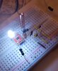
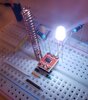
I finally got some time to put this together. for a novice im proud to say that this worked on the first try.
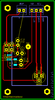
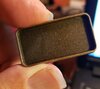
ive attached 2 additional breadboard views and the PCB. Its odd shape is designed to fit into a small project box. I designed the touch pad into a fabricated copper spring. that spring will be 1.5" when the larger plate compresses against it. The springs purpose is so the module can be eaisly serviced. On the pcb is also a bi-color led. it will be mounted in the plate. when the user touches the plate another circuit will change the leds color. The led will not be soldered on the board but inserted into a 3 pin female socket. The pcb also has two components on the opposite side for power and the leds signal from the other circuit.
The sensitivity adjustment range is 2.5-50pf. i selected 20pf and the response is perfect. no hovering trigger. only a light physical touch triggers the TTP223. I believe this layout best suits what this IC was designed for. im very pleased with how it turned. You have all taught me so much. I cant thank you enough.
This site uses cookies to help personalise content, tailor your experience and to keep you logged in if you register.
By continuing to use this site, you are consenting to our use of cookies.

")