Continue to Site

Welcome to our site!

Electro Tech is an online community (with over 170,000 members) who enjoy talking about and building electronic circuits, projects and gadgets. To participate you need to register. Registration is free. Click here to register now.

  • Welcome to our site! Electro Tech is an online community (with over 170,000 members) who enjoy talking about and building electronic circuits, projects and gadgets. To participate you need to register. Registration is free. Click here to register now.

Trying to spy CAN BUS in Ford EDGE 2013

Kovansky

New Member
Greetings to all,

In advance I want to mention that my English is not very good so sorry if you don't understand everything.

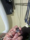
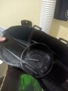
I currently have a Speedometer from a 2018 Ford Edge, which I want to get working.

When you power it with 12V it doesn't work, this is because (as far as I understand) it is waiting for a CAN message to start up.
Unfortunately I have not been able to find any CAN messaging service on the internet that can do it.

I currently own a 2013 Ford Edge SEL V6 AWD.

So I decided to use my Edge to read all the data from the CAN bus and from there separate everything I can (I'm relatively new and I'm learning how all this works, I'm only an electronics technician).

The problems I am having when reading the CAN bus of my vehicle are the following.

Problem #1 - First device:
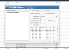
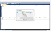
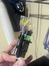
CAN to USB-C (CANABLE) using the PCAN-View software

When connecting the device to the CAN network, the vehicle shows many errors in the ODO and then the EDGE shut off a few seconds later, (it does nothing until i disconnect the CANABLE device from the CAN network and remove and reincert the key).
Watch video to understand better.

Problem #2 - Second device:
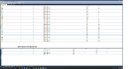
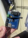
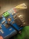
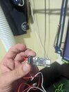
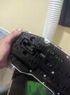
Clone of Arduino UNO and CAN BUS SHIELD.
With this I can see something of the CAN network but nothing close to the screenshots that you show in this forum.

I would like to know what I am doing wrong? I want to be able to read the CAN BUS data, an example is the video that pyrocrazy130 uploaded (Bo Gifford - Ford CAN bus hacking, comment #20) on this forum)

https://drive.google.com/drive/u/0/folders/1i2J3tV6eE-K8bA-D6dOocOT7jBDU7269 (pics, videos and more info of the device)

--> Update
After trying various configurations with the CAN to USB-C (canable), I managed to get the vehicle to not show the errors shown in the video "Problem #1 - First device" and to turn on without problems
 

Attachments

  • Arduino UNO and CAN BUS SHIELD-1.jpg
    Arduino UNO and CAN BUS SHIELD-1.jpg
    1.7 MB · Views: 102
  • Arduino UNO and CAN BUS SHIELD-2.jpg
    Arduino UNO and CAN BUS SHIELD-2.jpg
    3 MB · Views: 99
  • Arduino UNO and CAN BUS SHIELD-3.jpg
    Arduino UNO and CAN BUS SHIELD-3.jpg
    3.9 MB · Views: 107
  • CAN to USB-C (CANABLE) - 1.jpg
    CAN to USB-C (CANABLE) - 1.jpg
    3.5 MB · Views: 96
  • CAN to USB-C (CANABLE) - 2.jpg
    CAN to USB-C (CANABLE) - 2.jpg
    2.9 MB · Views: 98
  • Speedometer-1.jpg
    Speedometer-1.jpg
    2.5 MB · Views: 84
  • Speedometer-2.jpg
    Speedometer-2.jpg
    2.5 MB · Views: 98
Ensure that the CANable device is configured correctly, including the bitrate settings. Make sure you are not inadvertently sending disruptive messages to the bus. Reading data on the CAN bus with an Arduino requires proper initialization and configuration of the CAN bus shield. Confirm that the CAN bus shield and Arduino are properly connected and that you've configured the correct bitrate.
 
You definitely need a separate device to read the CANbus to make sure that you are sending stuff correctly with the Arduino. A Picoscope will do. Microchip make a cheap CANbus analyser.

A CAN log from a real car that has one of those speedometers is a massive help. Make sure that you get the correct CANbus. I would expect about two CAN buses on a 2013 Ford, but the circuit diagram will help. Without any information you are guessing.

A lot of Ford modules use signals in the range 0x580 - 0x5FF to keep modules awake. If you send any 8-byte frame in that range, every 500 ms or more often, the modules will stay awake. If the module that you have transmits a frame every 200 ms in the 0x500 - 0x57F range then it probably uses a different protocol to keep the modules awake. If so, it's a bit more complicated to keep the module awake. If you do see a messages in the 0x500 - 0x57F range, post what you find here and I can describe what you need to keep the module awake.
 
Thanks guys,

I'm going to look for the correct configuration for the Arduino Shield and the CANable device in the case of my Ford and continue testing and I'll tell you if I get an read the data.
 
UPDATE

After testing various connection configurations, these are the results.

1) with the Arduino uno & CAN BUS - SHIELD.
Not Working

2) CANable to USB-C (I tried all the configurations and one worked, I attach all the information).

After validating the CAN BUS with CANable configuration, follow the following route.

1) Start recording the PC-CANView program when Ford was not writing anda in the CAN (All empty-clear).
2) Press Unlock on my Key.
3) Enter vehicle.
4) Insert the Key.
5) turn the key to ON (But it doesn't start).
6) Waiting for the verification of vehicle.
7) Start.
8) Driving some minutes
9) Stop vehicle (Still running) and put in neutral (here save TRC file "RACERT FORD EDGE - Driving some minutes.trc")
10) Put vehicle in "D" and still driving.
11) finish my trip, stop vehicle, put in Parking and turn off the vehicle.
12) Go out.
13) Press Lock botton.
14) Here save TRC file "RACERT FORD EDGE - Driving some minutes-2.trc

Note: The file "TRACERT FORD EDGE - Unlock and entry to vehicle.trc" and "TRACERT FORD EDGE - TEST .trc" was for make some test, but i upload in case you need them.

Tracer file of my vehicle (Ford edge 2013) :
Drive: https://drive.google.com/drive/folders/1wO986q_gQxeerlSz7jfgHL1bBCuCxZzF?usp=drive_link
Mega: https://mega.nz/folder/alNTSSKR#M8Nw-Knz0XLh8dXYw_qh2g

Now I'm going to try to use those messages to turn on the ODO 2018.
 

Attachments

  • Ford CAN CONFIG CONNECTIONS.png
    Ford CAN CONFIG CONNECTIONS.png
    183.2 KB · Views: 95
You definitely need a separate device to read the CANbus to make sure that you are sending stuff correctly with the Arduino. A Picoscope will do. Microchip make a cheap CANbus analyser.

A CAN log from a real car that has one of those speedometers is a massive help. Make sure that you get the correct CANbus. I would expect about two CAN buses on a 2013 Ford, but the circuit diagram will help. Without any information you are guessing.

A lot of Ford modules use signals in the range 0x580 - 0x5FF to keep modules awake. If you send any 8-byte frame in that range, every 500 ms or more often, the modules will stay awake. If the module that you have transmits a frame every 200 ms in the 0x500 - 0x57F range then it probably uses a different protocol to keep the modules awake. If so, it's a bit more complicated to keep the module awake. If you do see a messages in the 0x500 - 0x57F range, post what you find here and I can describe what you need to keep the module awake.
I have a question.

I would like to better understand the CAN BUS messages, when you say "in the range 0x580 - 0x5FF to keep modules awake" what does it mean 0x580 or 0x5FF, how does it translate to the trace file I have?

How can I send it through the CANable Device? (see attached photo)
 

Attachments

  • Capture PC-CANVIEW Send.PNG
    Capture PC-CANVIEW Send.PNG
    44.3 KB · Views: 81
UPDATE

Applying the same configuration that I had on my FORD EDGE (for the connection), on the 2018 ODO that I have, I can now see the information that the ODO is sending through the CAN bus, I am attaching it here so you can help me identify it.

I upload the tracert file in my drive and mega.
 

Attachments

  • Speedometer FORD EDGE 2018 CAN BUS pic.png
    Speedometer FORD EDGE 2018 CAN BUS pic.png
    160 KB · Views: 103
I have a question.

I would like to better understand the CAN BUS messages, when you say "in the range 0x580 - 0x5FF to keep modules awake" what does it mean 0x580 or 0x5FF, how does it translate to the trace file I have?

How can I send it through the CANable Device? (see attached photo)
CANbus messages on cars normally have 11 bit identifiers (IDs). Those are often written in hexadecimal, and the range is 0x000 to 0x7FF (although the end values of 0x000 and 0x7FF aren't used). On the CANable device, the ID is entered in the box on the left.

My suggestion for keeping the speedo awake is any ID between 0x580 and 0x5FF. The data length should be 8, and the cycle time should be 500 ms. The actual data doesn't matter.

If the module behaves as I expect, you can use any of the 128 IDs in the range 0x580 to 0x5FF, so 0x580, or 0x581 or 0x582 and so on up to 0x5FE or 0x5FF.

The modules are programmed to stay awake if an ID in that range is received. That gives the system flexibility so that all the module will stay awake at the same time, even if the exact combination of modules varies with different options, or even if one module fails.
 
1703542368854.png

That comes from TRACERT FORD EDGE - Driving some minutes-2.

It is from frame ID 0x260 byte 1 concatenated with the top nibble of byte 2

For instance, at 17493.8 ms, frame 260 had a value of 00 1F E0 00 00 00 00 00, so they signal I took would have been 0x1FE. That has a decimal value of 510.

My best guess is that the signal represent throttle position.
 
Later I will take video of the ODO (of the Ford Edge) while I drive so you have a better idea of the trace.
I ask, how do you transform the tracer data into that graph??
 
Later I will take video of the ODO (of the Ford Edge) while I drive so you have a better idea of the trace.
I ask, how do you transform the tracer data into that graph??
I used a spreadsheet to sort the data so that all the frames from one ID were together, and in time order.

Then I looked for data that was changing. Within the changing data, I looked for where values went from FF to 00 and then found other values that increased by 1 each time that happened.

1703570573640.png

Here byte 2, the right hand column only has the top half changing. There are two instances where it goes from a larger number to a smaller number and at the same time byte 1 increases by 1.

F -> 4 while 0 -> 1
C - >7 while 1 -> 2

( A very short time later byte 2 goes from B to A and byte 1 does not change, but I think that the value being represented had stopped changing at that point, as there were two instances of B before that)

Anyhow, I used that observation to apply this formula to all the data.

=HEX2DEC(E1)*16+HEX2DEC(F1)/16

(column E is byte 2 and column F is byte 3. I copied that down the whole of the data from the 0x260 frame, and plotted a graph of that against the time from the first column.
 
I've found what I am virtually certain are the speed signals from the four wheels.
Frame 0x215 has the four speeds, each as a 2 byte number, in units of 0.01 kph and it is sent every 10 ms. This is what I have seen on other cars, such as a Jaguar X-type, which was Ford based architecture.

All four wheel speeds are similar, but there are slight differences when you look in detail, likely due to slight differences in wheel diameter, plus the speed differential in corners.

There may be other speed signals, so these might not be what the speedometer responds to.

1703583189268.png
 
I've found what I am virtually certain are the speed signals from the four wheels.
Frame 0x215 has the four speeds, each as a 2 byte number, in units of 0.01 kph and it is sent every 10 ms. This is what I have seen on other cars, such as a Jaguar X-type, which was Ford based architecture.

All four wheel speeds are similar, but there are slight differences when you look in detail, likely due to slight differences in wheel diameter, plus the speed differential in corners.

There may be other speed signals, so these might not be what the speedometer responds to.

View attachment 143817
Yes, the area where I live has many curves, perhaps that is why the slight differences related to the differential.

Right now my CANABLE device was broken and not working well (I tried to do a firmware update and I broke it), I ordered two new ones but they arrive in the first week of January.

When I arrive, I plan to make a continuous journey of at least 5m while I recorder in video the ODO (Ford edge 2013) and also the data via CANBUS.

Another thing, can you share that Excel sheet with me, I tried to copy and paste part of the data obtained from the CAN BUs but the Excel becomes quite slow and does not work as expected.

At the moment this is the list of IDs that have worked for me when I send signals to the ODO 2018 (the one I have connected via CAN-USB on my PC).

Encender el ODO (Turn on the ODO and do another thing)
------------------------------------------------------------
PC-CANVIEW (Parameters format paste in the CANVIEW Software)
------------------------------------------------------------------------------
ID=76,Type=D,Length=8,Data=10AFFF,CycleTime=500,IDFormat=hex
ID=531,Type=D,Length=8,Data=FFFF00008011FF41,CycleTime=500,IDFormat=hex
ID=C,Type=D,Length=8,Data=40,CycleTime=500,IDFormat=hex
ID=948,Type=D,Length=8,Data=401111FF2020,CycleTime=500,IDFormat=hex
ID=1057,Type=D,Length=8,Data=0040014000000580,CycleTime=500,IDFormat=hex
ID=1046,Type=D,Length=8,Data=05000FE00010,CycleTime=500,IDFormat=hex
ID=76,Type=D,Length=8,Data=10AFFF,CycleTime=500,IDFormat=hex
ID=947,Type=D,Length=8,Data=4088001210008002,CycleTime=450,Paused=1,IDFormat=hex

===========================================================
>>>>>>>>>>>>>>>>>>>>>>>>>>>>>>>>>>>>>>>>>>>>>>>>>>>>>>>>>>>>>>>>>>>>
Eliminar alerta de Bolsa de Aire en el ODO (Remove the Airbag warning light)
>>>>>>>>>>>>>>>>>>>>>>>>>>>>>>>>>>>>>>>>>>>>>>>>>>>>>>>>>>>>>>>>>>>>
PC-CANVIEW
ID=76,Type=D,Length=8,Data=10AFFF,CycleTime=500,IDFormat=hex
CAN BUS Message
76 4C 8 10 AF FF 00 00 00 00 00 HS-CAN, HS-CAN2 Airbag Indicator Light

>>>>>>>>>>>>>>>>>>>>>>>>>>>>>>>>>>>>>>>>>>>>>>>>>>>>>>>>>>>>>>>>>>>>
Eliminar sensor de presion de neumaticos (Remove the Air tire warning light)
>>>>>>>>>>>>>>>>>>>>>>>>>>>>>>>>>>>>>>>>>>>>>>>>>>>>>>>>>>>>>>>>>>>>
PC-CANVIEW
ID=948,Type=D,Length=8,Data=401111FF2020,CycleTime=500,Paused=1,IDFormat=hex
CAN BUS Message
948 3B4 8 40 11 11 FF 20 20 00 00 HS-CAN

>>>>>>>>>>>>>>>>>>>>>>>>>>>>>>>>>>>>>>>>>>>>>>>>>>>>>>>>>>>>>>>>>>>>
Eliminar sensor de Freno de parqueo (Remove the Parking warning light)
>>>>>>>>>>>>>>>>>>>>>>>>>>>>>>>>>>>>>>>>>>>>>>>>>>>>>>>>>>>>>>>>>>>>
PC-CANVIEW
ID=531,Type=D,Length=8,Data=FFFF00008011FF41,CycleTime=500,IDFormat=hex
CAN BUS Message
531 213 8 FF FF 00 00 80 11 FF 41 HS-CAN, HS-CAN2

>>>>>>>>>>>>>>>>>>>>>>>>>>>>>>>>>>>>>>>>>>>>>>>>>>>>>>>>>>>>>>>>>>>>
Eliminar testigo del ABS (en amarilllo) y elimina el testigo del AdanceTrac Service
(Remove the ABS "Yellow" warning light and AdanceTrac Service warning light)
>>>>>>>>>>>>>>>>>>>>>>>>>>>>>>>>>>>>>>>>>>>>>>>>>>>>>>>>>>>>>>>>>>>>
PC-CANVIEW
ID=1046,Type=D,Length=8,Data=05000FE00010,CycleTime=500,Paused=1,IDFormat=hex
CAN BUS Message
1046 8 50 00 FE 00 01 00 00 00 HS-CAN, HS-CAN2

>>>>>>>>>>>>>>>>>>>>>>>>>>>>>>>>>>>>>>>>>>>>>>>>>>>>>>>>>>>>>>>>>>>>
Eliminar testigo del Check Engine (en amarilllo) y elimina el testigo del LOW Engine Oil Preasure
(Remove the Check Engine "Yellow" warning light and LOW Engine Oil Preasure warning light)
>>>>>>>>>>>>>>>>>>>>>>>>>>>>>>>>>>>>>>>>>>>>>>>>>>>>>>>>>>>>>>>>>>>>
ID=1057,Type=D,Length=8,Data=0040014000000580,CycleTime=500,Paused=1,IDFormat=hex
CAN BUS Message
1057 8 04 00 14 00 00 00 58 00 HS-CAN

>>>>>>>>>>>>>>>>>>>>>>>>>>>>>>>>>>>>>>>>>>>>>>>>>>>>>>>>>>>>>>>>>>>>
Enciende el testigo del Transmission Malfunction Service Now
(Turn on the Transmission Malfunction Service Now "Left Screen Warning" Not light)
>>>>>>>>>>>>>>>>>>>>>>>>>>>>>>>>>>>>>>>>>>>>>>>>>>>>>>>>>>>>>>>>>>>>
ID=1072,Type=D,Length=8,Data=03701B9AAC05E375,CycleTime=500,IDFormat=hex
CAN BUS Message
1072 8 37 01 B9 AA C0 5E 37 5C HS-CAN, HS-CAN2
3701B9AAC05E375C

ID=1072,Type=D,Length=8,Data=3701B9AAC05E375C,CycleTime=500,IDFormat=hex

>>>>>>>>>>>>>>>>>>>>>>>>>>>>>>>>>>>>>>>>>>>>>>>>>>>>>>>>>>>>>>>>>>>>
Enciende la aguja de los kilometros.
(Turn on the light of center of ODO - The speed needle)
>>>>>>>>>>>>>>>>>>>>>>>>>>>>>>>>>>>>>>>>>>>>>>>>>>>>>>>>>>>>>>>>>>>>
ID=947,Type=D,Length=8,Data=4088001210008002,CycleTime=450,IDFormat=hex
CAN BUS Message
947 3B3 8 40 88 00 12 10 00 80 02 HS-CAN

I don't know
ID=947,Type=D,Length=8,Data=4088001210008002,CycleTime=500,Paused=1,IDFormat=hex ???
ID=947,Type=D,Length=8,Data=4088001221008002,CycleTime=500,Paused=1,IDFormat=hex ???

ID Testing
ID (hex) ODO 2018
135
291
395
400
403
405
410
494
498
504
505
506
507
508
544
549
647
676
756
765
778
783
787
789
790
791
792
838
840
848
851
867
968
992
1019
1072
1076
1114
1425

Another testing.
I saw in other forums these IDs are for: (But i'm not sure if work)
0x430 Fuel level
0x433 Driver and passenger dor opened
0x420 Coolant temp
1703716610815.png


1703716660811.png
 
The Excel sheet for the whole log is quite large. The one for the speed only is here:-

https://mtrak.co.uk/pictures/215_frame.xls

You can use Excel or Notepad++ to sort the data so that all the frames with the same ID are together. In Notepad ++ you can search the .trc files for

Rx 0215

Just select one instance of that from the file, then copy, ctrl-F to find, paste into the find box, and click on "Find All in Current Document

I have found it better to have short traces of about 30 seconds where you have made something happen during the trace. Maybe altered the speed, or started the engine or something. Files of that size are much easier to handle in Excel. If you have a 5 minute trace with a video that will be much more difficult to find events in than 10 traces and 10 videos, each of which has a known event in.

Your car has the wheel speeds on the frame with ID 0x215. The Jaguar X-type that I looked at before had the wheel speeds on ID 0x4B0, which is the same as on the list that you found. However other details are not. You have to check any IDs that you use as they may change between models and years.

I think that there is some confusion between decimal IDs and hexadecimal IDs. On cars, the 11 bit CANbus IDs are used, which go up to 0x7FF, which is 2047 in decimal. The last item in your list is 1425, which is 0x591 in hexadecimal. That is the frame number of the message used to keep the speedo awake. I suggest you stick to hexadecimal IDs.
 
Last edited:

Latest threads

New Articles From Microcontroller Tips

Back
Top