Continue to Site

Welcome to our site!

Electro Tech is an online community (with over 170,000 members) who enjoy talking about and building electronic circuits, projects and gadgets. To participate you need to register. Registration is free. Click here to register now.

  • Welcome to our site! Electro Tech is an online community (with over 170,000 members) who enjoy talking about and building electronic circuits, projects and gadgets. To participate you need to register. Registration is free. Click here to register now.

Trying to improve PSU regulation

Status
Not open for further replies.

TheOne

New Member
I found this in the projects section, and looking quite simple to build for a beginner, I wondered how good the regulation would be.
https://www.electro-tech-online.com/threads/searching.176/
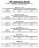
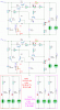
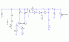
So once again I fired up my simulator and made some measurements. The regulation at full voltage (15V@1A) wasn't bad at 0.4%. This figure got worse as the voltage was lowered while maintaining 1A current. (I disconnected the current limit for the measurements). Looking at the circuit, I wondered what simple modification could improve the performance? The first obvious thing I spotted was the 1K resistor in the long-tail pair. So I decided to replace this with a constant current source (for obvious reasons). A simple way is to operate a Jfet at it's Idss current by tying the gate to source. This is about 10mA for the Jfet used.

After doing this, I evaluated the performance again near the lowest voltage and the highest voltage setting. This time the % Voltage regulation improved to 0.32% at about 15V and quite a bit to 0.4% from the original 8.7% at about 7V. Ripple rejection ratio improvement was less spectacular to 29dB from 21dB

If someone on this forum actually constructed this PSU, it would be interesting to get feedback regarding the performance before and after the proposed mod.

One last thing, I reduced the value of the current sensing resistor as I could not get a full 1A before the foldback kicked in.
 

Attachments

  • stab_psu.gif
    stab_psu.gif
    42.6 KB · Views: 1,001
PSU Design

It's refreshing to see someone actually testing the operation of one of these circuits and suggesting improvements ...

I fully appreciate your work here and don't mean to dismiss your efforts but if you want to improve the long-tailed pair would it not be better to simply swap it for a 741 op-amp and benefit from a vastly improved gain :?:

With any design there has to be a trade-off between complexity and performance, a dual-rail, tracking design would be nice -- but complex :?:
Would it ? ... thinking caps on lads - I start to see a circuit with a 741 and 7805/7905 :?

The original circuit was my main (only) bench power supply for a number of years - I may still have it somewhere in the attic, if I can find it I will see if I can test the FET idea and get back to you (but don't hold your breath - it could take WEEKS to find and MONTHS to get time :shock: ).
 
You can dramatically raise the gain and temperature stability of the discrete op amp with a transistor array (CA3046), which improves both line and load regulation. I added a cap (C1) which improves ripple rejection even more. Get rid of the cap (C2 in the original schematic) from the feedback node to ground. It makes the supply unstable if you add a capacitive load (which you will). I found in my sims that 470uF or greater from output to GND provides best stability (in the frequency domain).
I didn't show the wipers on the pots in my schematic.
In the simulation of the circuit below, supply rejection was about 62dB, and load regulation was about 0.016% for 0 to 1 amp load change. This was at maximum voltage (about 14.7V), which is the worst case for both.
As Mechie said, an integrated op amp would probably be a simpler solution, and current limiting could probably be improved by usind another one.
I have a dual tracking power supply at home that I made by modifying the +15V and -15V supplies in my breadboard (plugboard?). I'll see if I can dig up the schematic. The pass elements are 7805/7905, so it is pretty much bullet proof.
 

Attachments

  • improved_psu.gif
    improved_psu.gif
    8.9 KB · Views: 1,022
I know there are many ways to improve the design but my idea was that if someone already made a pcb for the original design, by just sticking in the Jfet into the holes of the resistor without major modifications he may benefit from the improved regulation.

My R.R meaurements were made with no output caps.

I was in no way trying to redesign the PSU. I think it is a good easy circuit for as beginner to construct and understand.
 
TheOne said:
I know there are many ways to improve the design but my idea was that if someone already made a pcb for the original design, by just sticking in the Jfet into the holes of the resistor without major modifications he may benefit from the improved regulation.

My R.R meaurements were made with no output caps.

I was in no way trying to redesign the PSU. I think it is a good easy circuit for as beginner to construct and understand.

The impedance of the tail current source will have little effect on this circuit, because the voltage across it never changes (1st order). The first problem is with the value of the collector load resistor (R3, 2.2k) in the diff amp (original design). It is much too low for the value of the tail current. It either needs to be larger, or the tail current needs to be more. As originally designed, it starves TR1 when the output voltage is set low. The tail current is always 4ma, so ideally, the current through R3 should be 2ma, so the diff pair trannies see 2ma each. This can't happen with a resistive load and a variable output voltage. The best compromise is about 6.2k. See results in the first schematic below.

The real single-component solution for improvement in performance is to change R3 to a current source. This raises the loop gain by a bunch, with the results shown in the second schematic.

I used the **broken link removed** because they had a spice model, but **broken link removed** has what I believe is an equivalent part. I drew it as a jfet, because I could then easily assign the model to it, but I think the mfrs use a different symbol.
Note that both have a knee voltage of 6 volts, so the unregulated supply can't drop much below 24V without adverse effects.
You still need to get rid of the 470nF cap on the feedback node, for the reason I stated previously. With loop gain lower than my original circuit (with the CA3046), minimums of 10uF and 100uF, respectively, were needed on the outputs of the two versions of the circuit for stability.
 

Attachments

  • psu_njf.gif
    psu_njf.gif
    7.6 KB · Views: 884
  • psu1_6k2.gif
    psu1_6k2.gif
    7.6 KB · Views: 884
Hi Ron, Nice analysis. I don't get nearly as good R.R with your circuit in my simulation program. V.R is closer. Which program are you using?
 
TheOne said:
Hi Ron, Nice analysis. I don't get nearly as good R.R with your circuit in my simulation program. V.R is closer. Which program are you using?
I'm using Linear Technology's SwitcherCAD III (its primary virtue is that it's free). I have no way of knowing (other than manual calculation - yeah, right) if it is correct. I did check ripple rejection with both AC analysis (1kHz to 10MHz sweep) and transient analysis (120Hz, 1V p-p sine wave on 25V dc), and got the same answers. I think the difference between your results and mine may have to do with the transistor models we are using. I inadvertently left in the CA3046 NPNs on my sims. I have since replaced them with 2N3904s and have gotten better regulation. I suspect the different zener models may account for the ripple rejection differences.
I had another idea. I replaced the zener bias resistor with another 2ma constant current diode, and the ripple rejection improved to 63dB @ max output (now 14.2V, due to reduced zener voltage at 2ma), and to 73dB @ min output.
 
I suppose the best next thing would be to build it and make measurements :) . I will try to get hold of another program to compare. My one friend uses software by Ansoft for PSU's so maybe he can compare results.

I must say that the software I am using proved quite accurate the times I took trouble to verify the results by actual measurements. I have found a few instances where some models were too good to be true, which just again prove know what to expect and not to believe everything a spice program spits out.

What were your results with the original circuit as is?
 
TheOne said:
I suppose the best next thing would be to build it and make measurements :) . I will try to get hold of another program to compare. My one friend uses software by Ansoft for PSU's so maybe he can compare results.

I must say that the software I am using proved quite accurate the times I took trouble to verify the results by actual measurements. I have found a few instances where some models were too good to be true, which just again prove know what to expect and not to believe everything a spice program spits out.

What were your results with the original circuit as is?
If you can post models for the transistors and zener in the original schematic, I can try it. I don't have any of them. I cheated on the BD131 - I found a model for BD132, the PNP complement, and changed it to an NPN. :roll: For the rest of the parts, I just used some general purpose stuff, as you can see.
 
The moment I can find a way to extract the model data I will PM it to you.

I just looked at the specs of one of the expensive (almost month's salary for most people :) ) older HP (not Agilent) supplies in the lab. They quote %V.R at only 0.03% at 15V @ 1A and R.R at about 65dB and the circuit look a hell of a lot more complicated (opamp's, temp compensated references etc.) than the one we are playing with. Makes me wonder....

Later model Philips programmable supply is better at 0.01% but R.R a bit lower by 2dB.
 
OK, the results are in! I asked someone who uses Agilent's ADS program to run the simulations for me. This is a high dollar value program and one of the industry standards used by many big companies. All the models for the components used came from the libraries supplied with the program by Agilent so I assume (hope) they will be quite accurate.

I am pleased to learn that the figures obtained from my simulations were very close. I only evaluated ripple rejection at full load in my original simulation. In the table there are figures for no and full load. Ripple rejection was only evaluated at 120Hz as that is what the supply would most likely see from full the wave rectifiers.

The 4.5dB spec is interesting. I have asked to have that checked again and that is what it reports :? The figures for 1Vp-p sine were: NL - 0.593Vp-p FL - 0.101Vp-p

EDIT: Just checked my own program. Not quite as bad. NL 0.4Vp-p and FL 0.1Vp-p. Ron, any ideas?
 

Attachments

  • psu_results.gif
    psu_results.gif
    20.9 KB · Views: 748
On the original circuit, I get 238mv p-p at no load, and 133mv p-p at full load. Both waveforms have a fair amount of even harmonic distortion, but I get comparable results with AC analysis.
As I mentioned previously, I don't have models for BC108, BD131, or BZY88C. I am still surprised at the large discrepancies with this circuit, where the 2.2k resistor should swamp out transistor collector impedance variations. With a current source load, collector impedance will have a bigger effect on loop gain, and hence ripple rejection.
Zener impedance will affect ripple rejection, but in my sim, the ripple on the zener was down 52dB. With the gain at max output, its contribution should still be down about 42dB at the output. This is consistent with my results for PSU_njf. You said you used 2 current sources on Improved_PSU. Was one of them the bias current for the zener? I can't see how you could get ~60dB ripple rejection otherwise.
 
Ron H said:
You said you used 2 current sources on Improved_PSU. Was one of them the bias current for the zener? I can't see how you could get ~60dB ripple rejection otherwise.
Yes, I believe that was the case. I wasn't present during the simulations as this guy is too far away from me.
 
Status
Not open for further replies.

Latest threads

New Articles From Microcontroller Tips

Back
Top