Electro Tech is an online community (with over 170,000 members) who enjoy talking about and building electronic circuits, projects and gadgets. To participate you need to register. Registration is free. Click here to register now.
Welcome to our site! Electro Tech is an online community (with over 170,000 members) who enjoy talking about and building electronic circuits, projects and gadgets. To participate you need to register. Registration is free. Click here to register now.
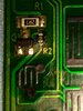
After cleaning and lighting PCB from bottom side with my camera flash on phone, I have found that track is clearly broken on joint with resistor R2. Cut is a size of a hair, so how to repair this?
After cleaning and lighting PCB from bottom side with my camera flash on phone, I have found that track is clearly broken on joint with resistor R2. Cut is a size of a hair, so how to repair this?
Done it. Just need to solder it, in a couple of days.
I have verified that is the broken spot, so I just need to solder it and it'll work.
Thanks for help, I appreciate it.
Well, I didn't succeed in soldering.
I followed advice and tried to put blob of solder on broken spot but everything melted and both resistors slided off, and now I can't put them back.
I don't have experience with SMD components, so I am not able to solder them back, even though connections are still ok, and it is possible to put resistors back, but I can't because they are too small and I don't have skill to do it.
Here are pictures before and after.
How to clean residue?
I don't know until I clean residue if pads for R2 are damaged.
I used 60W soldering iron, I have 30W also, probably should've used that one, but first time when I tried to put solder for a second, everything melted right away.
This is what it looks like after cleaning residue.
Pads for R2 are missing, right pad for R1 is also missing.
Is there a hope that I can still put back on resistors?
That's a real disaster. You know you can't solder to the green stuff (solder resist). It has to be scraped off to expose the copper. You used WAY too much heat.
At the very least, you need a solder braid to remove solder. Chip-quick makes a desoldering alloy that lowers the temperature.
You would need to clean the board up better and scrape the traces to expose the copper. The component can be glued using superglue. Real component glue will shear if you twist the component.
Wire-wrap wire is used a lot of times to make repairs.
ROHS solder is high temperature and is difficult to work with. Sn96 is reall tough to work with. Solders containing a bit of Bismouth (Bi) tends to have a much lower melting point.
Actually, the two temperatures are called solidus and liquidus points. In the 63/37 lead alloy solder the points are the same and it instatly solidifies" It's a great alloy to use for IC's. Tin (Sn) lead (Pd) 60/40 was very common and easy to work with.
Wire solder has "cores" of flux. flux cleans and prevents the surface from oxidizing. It also needs to be removed after the operation is complete,
Rosin, no clean and water clean up are available. The sooner the flux is removed, the easier it is.
It's not a disaster, it's a Chernobyl.
I never worked with SMD components before, I didn't expected them to melt and slide off right away, I wasn't even that close to resistor R1 and it slided off.
I am surprised that transistor stayed in place.
I think I can repair it, but I must be carefull and I need to do it right.
I will superglue resistors in place and scrape off traces to solder wires to resistors.
But before I do that, I will have to learn little bit about SMD soldering, I didn't have any experience with them before this.
My very first SMD component replacement was a 40 pin CPU chip in an automotive radio.
My first C program was an operating system and instruction set simulator (group of 2)
My firat 1802 program was routines to allow subroutines. The processor has no gosub/return statements, but any register can be the program counter or stack pointer. It was hand assembled without a compiler.
I put an AC system in a car from a "box of parts". That was fun.
SMD soldering in mass production is done with a stencil and solder paste. You squeegee solder paste onto the PCB thenit gets heated in an oven with a particulat time-temperature profile.
In order to repair board, I need to reinstall pads for SMD resistors.
There is in electronic shop a copper foil thickness 0.05 mm that is one side adhesive.
I was thinking of solder this foil to trace and stick foil to pad spot.
In theory it seems like it works. There was an entire make your own PCB with tape available many years ago. The adhesive was the problem. Locktite Tak-Pak and wire wrap wire has been a way to make PCB changes for a while.
Remember that the PCB material can be a Fiberglass Epoxy mix
So, epoxy isn't a bad adhesive. Superglue isn't great for permanent repairs, but the components are generally removeable because of the heat.
Just replace the SM resistors with small (1/10th watt?) wire ended ones, soldered directly to the remaining bits of track - cleaning and tinning them first of course. Small wire ended resistors should be plenty small enough.
This site uses cookies to help personalise content, tailor your experience and to keep you logged in if you register.
By continuing to use this site, you are consenting to our use of cookies.

 ) is good for this.