Continue to Site

Welcome to our site!

Electro Tech is an online community (with over 170,000 members) who enjoy talking about and building electronic circuits, projects and gadgets. To participate you need to register. Registration is free. Click here to register now.

  • Welcome to our site! Electro Tech is an online community (with over 170,000 members) who enjoy talking about and building electronic circuits, projects and gadgets. To participate you need to register. Registration is free. Click here to register now.

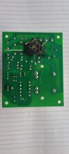
Trying to fix the powerboard of a Kegerator

Cowboy44

New Member
I have a Kegerator (a small fridge for home brew) and it appears the starter relay failed.

The powerboard is a Yirui BF163 DY (China).

I have a replacement so I have cold beer again which is the main thing, but I'd like to try and repair the board.

I'm trying to find a wiring diagram for the circuit if possible. I'm not an electrical engineer or electrician, but I do have a technical background.

Any assistance would be appreciated, even if it's advice to just toss it and move on :)

thanks

Michael
 

Attachments

  • 20240603_080455.jpg
    20240603_080455.jpg
    1.2 MB · Views: 208
  • 20240603_080446.jpg
    20240603_080446.jpg
    1.1 MB · Views: 175
I think that all that is wrong is a burned-out connection to the relay.

The large yellow and black item is a transformer that produces low-voltage electricity to run the electronics. The electronics control when the fridge compressor runs. The blue relay has a low-voltage coil, controlled by the electronics, and the relay is what actually switches the compressor on and off.

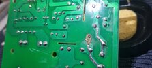
The tracks on the board go from the L connection, through the relay, and to the Comp connection. These tracks have to take more current than anything else on the board, and if there is a bad connection, there will be a lot of heat.

The weight of the relay along with vibration has probably stressed the connection, and then the heat from the damaged connection has caused it to burn out.

You probably just need to
1) clean off the black marking, which will conduct electricity, so could cause a short.
2) solder wires in place of the burned-out track.

It's possible that the fuse has blown which will need unsoldering and replacing. Test the continuity to see if it has blown.

The relay could be damaged, either if the pin is burned off, or it could have been damaged as the heat built up, or it could have been the cause of the heat that initially weakened the solder joint. Relays like that aren't repairable, but they are easy enough to find replacements for. Unsoldering them is a bit tricky as you need to get solder off all of the pins.
Thanks Diver300 !!

Once I cleared the blast radius with Iso, I could clearly see a burnt leg on the starter relay. Looks like just replacing the SMI-S-112LM 4 pin (some have more) starter relay and run one wire back to the fuse, that'll fix that part.

It looks OK, but I'll check the fuse anyway.

Thanks for your help! I haven't had to fix a circuit board like this since I was an apprentice tech, too many years ago...

Really appreciate it. Thank you.
 

Attachments

  • 20240604_165503.jpg
    20240604_165503.jpg
    2.4 MB · Views: 155
The molten copper and carbon spray pattern suggest something like a few hundred amp short to something like an exposed ground plane. It evaporated the annular ring and part of the relay pin
1717545920323.png
 
Last edited:
The molten copper and carbon spray pattern suggest something like a few hundred amp short to something like an exposed ground plane. It evaporated the annular ring and part of the relay pin
Not at all, it's a completely standard failure mode, a dry joint on the relay pin causing sparking, I've seen it countless times on all kinds of equipment.

It's caused by flow soldering, which doesn't work very well on heavy/large parts like relay or transformer pins. If you properly hand solder the pins it will never fail - Bush introduced a modification on one of their TV's long ago, with similar problems on a pincushion choke, in their case they suggested resoldering the pin with high melting point solder (which is stronger).

In this case, simply clean the board, scrape away any carbon, and solder a wire from pin to PCB track - I like to use solid wire, and bend it round the pin.
 
Good point on the higher temperature or higher dwell time manual solder. Oxidized larger mass pins take longer to diffuse heat.
For wave challenges on large parts, aquawave ripple and pre-spray flux may improve cold solder yields.

So no parts might be damaged except the PCB trace with the sustained arc weld damage.

In general nothing is damaged other than the PCB itself, although there are the odd exceptions.

In particular a Sharp CRT TV used to suffer a 'burn-up' - I can't even remember what the component was who's pin caused it, but it was near the frame output IC heatsink - it was probably an S correction capacitor, or linearity choke?.

Anyway, it burnt a fairly big hole in the PCB, taking out various nearby components at the same time, simply from the heat and flames. I repaired a fair number of them, initially by cutting the burnt part of the board out, and wiring across the hole with solid cored wire, to replace the tracks. Then I connected new components to the floating wires, to recreate the original circuit.

Later on though Sharp brought out a repair kit, which came with a small PCB holding the damaged components, which you mounted on the nearby heatsink (as far as I can remember) - you then cut the damaged board out as before, and ran the wires from the new small board to the remaining parts of the burnt tracks.
 
Thanks Guys, I really appreciate everyone's input. I've tried on other forums for some helpful information and I may as well have been screaming into a back hole.

Thank you so much!
 

Latest threads

New Articles From Microcontroller Tips

Back
Top