Continue to Site

Welcome to our site!

Electro Tech is an online community (with over 170,000 members) who enjoy talking about and building electronic circuits, projects and gadgets. To participate you need to register. Registration is free. Click here to register now.

  • Welcome to our site! Electro Tech is an online community (with over 170,000 members) who enjoy talking about and building electronic circuits, projects and gadgets. To participate you need to register. Registration is free. Click here to register now.

Triangle wave (170Hz) generator's circuit requirement

Status
Not open for further replies.
1. Do you have any crystals available besides 32 kHz and 24 MHz?

2. What "exact frequency"? You have mentioned anything between 160 Hz and 180 Hz. Which exact frequency do you need?

ak
 
C-Mos 40.. serias doesn't work proper with frequencies above 1 - 1.5Mhz.
An 24Mhz crystal doesn't fit with this.
The 4060 should work with Your 32.xxx crystal, because it has an internal oszillator circuit.
So no external oscillator circuit is needed.
At the outputs Q3...Q13 the divided frequencies of the oscillator are availible.
Look here how to connect.

That an exact frequency of 160, 170, or 180 Hz difficult to generate with Your 32.678 Hz crystal, we talk some posts before.
 
Dear All,

Thank you very much for your positive response and kind help. Everyone give me suggestions and some good ideas, i am working on it and hope fully achieve good results soon. Maybe later i will ask something related to Integrator circuit by using LF353 op-Amp IC.

Once again Thank you very much for your kind cooperation.

Regards
Nomi
 
here's a variation on a divide by 3 of rjenkinsgb in this post... https://www.electro-tech-online.com...ators-circuit-requirement.158461/post-1371903

You said anything from 160 to 180Hz with the stability of a crystal is ok. That seems to be your biggest challenge, the ramp generator can easily be handled later.

Simply take your 32.768kHz crystal, make an oscillator from an inverter (e.g. 74HC14 Schmitt trigger inverter seems to work ok for this low frequency).

send that over to a divide by 16 chip (SN74LS93)

send that to a divide by 12 chip (SN74LS92)).

output will be 170.66Hz

- let me know if you need a ramp generator.

I set it up with some very old school DM7492 and DM7493 chips out of curiosity (wondering if these 45-year old chips work) and it worked like a charm as shown on my 35-year old scope.

you might be able to skip the inverter and 7493 chip if you get the cd4060 to work as your divider AND 32.768Hz oscillator. It should work if you power with 5v.


1568ED1D-4B7F-43F0-BE5A-C22BE12DE5C8.jpeg
 
Last edited:
Dear all,

Once again i am here asking for one question related to subject topic, as i asked previously asked previously that i am interested to design a 170 Hz triangle waveform generator by using 32.768Khz crystal oscillator, by your instructions and kind help i am success fully generated 170 Hz wave form but the shape of wave form is not pure triangular, Please find the attached cct and suggest me how can i get pure triangular wave with amplitude 0 ~ 4.5V/5V, what values and topology for RC network is good to achieve desired results. At f2 frequecny is 170 Hz and manitude is 0 ~5V but at output of LF353 (opamp) magnitude is bit lower. already spend too much time but didn't find the solution. please suggest me with your kind recommendations. Specially Thanks to gophert for your great effort.

Thanks
1582566158196.png
 
Your LF353 has an output that will stay about 1 to 1.5v about negative power supply and about 1.5 to 2.0v below positive supply. That doesn't leave much of a range if you are using a 5v supply. The datasheet says to use a 10v minimum (rail to rail) supply voltage).

the "virtual ground" on the + input to the op amp must be adjusted to put center of the output waveform where you want it. The 330 ohm resistor is optional but helps with jitter on the waveform.


9236B46F-EA0B-4A76-9DBA-51B064B32919.jpeg
 
Dear Respected @ gophert

Thank you very much for your kind help and reply. First i would like to tell you i have used +12 and -12 V as supply voltage of LF353. Secondly yor circuit seems much better. so i will work on it. if i feel any problem and i have any question i will contact you again respected gophert.

Again Thanks for your kind help and cooperation.

Regards
Nomi
 
Dear Respected @ gophert

I wanna ask one question i used your circuit and redraw in LTspice , But found an error. The screen Shot is attached for your reference please. if you need schematic, i can sent you.. Please where the error while same circuit is working well at your end.

1582648252525.png


Regards
Nomi
 
You will be using a split -12, 0, +12v I have a slightly different circuit for you. Give me until tonight.
 
Dear Respected @ gophert

Yes you are right i am using split supplies for +12V, -12V, & +9V. Your provided circuit is extremely good, i need the same one. Please take your time but suggest me must, how can i get the same results. schematic is attached for your reference please. You can review clearly. Once again Thank you very much for your kind help.

Regards
 

Attachments

  • Integrator with LF353.asc
    1.8 KB · Views: 139
The text is so small that I can't read any of the part numbers.

Dear Respected AnalogKid,

I have used LF353 Op amp which part number is not good visible. Dear AnalogKid i think form the above mentioned post you get the point what i need to design. In simple words i wanna convert square wave of 170Hz into Triangular wave of 170Hz.

Regards
 
Here.
your LF353 is a dual op amp. I assume the other half of the chip is available for the circuit.

I also assume you are powering logic chips that generate the 170Hz signal with 5v supply to get 5v square wave.

C59FA32E-0072-4203-8B74-8EDE03491418.jpeg
 
Hola gophert

What simulation program are you using?
 
Hola gophert

What simulation program are you using?

iCircuit for iPad + I think it is available as a windows 10 app as well.
all generic parts and supper fast/easy to put something together. It is the only app Iever paid for (5 or $10).
 
iCircuit for iPad + I think it is available as a windows 10 app as well.
all generic parts and supper fast/easy to put something together. It is the only app Iever paid for (5 or $10).
Thanks
Quite pleasant appearance. Looks more credible than LTSpice this way! :D:D
 
As mentioned in post #19, there are several circuit and component errors that will combine to slowly build up a DC charge on the integration capacitor and eventually saturate the opamp output either high or low. The solution is a DC servo that injects a small current into the opamp summing node (inverting input) to keep the output centered between the rails.

ak
I noticed that. I added the 1Mohm feedback resistor and that seemed to take care of it in simulation (although it adds an ever-so-slight hook to the ideally straight slopes of the triangle wave). I'll set it up to see how simulation and reality overlap. I think I even have a vintage LF353.
 
Dear respected gophert,

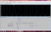
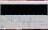
First of all Thank you very much for your kind help. This circuit is very effective for my requirement. I have designed in LTSpice, and when i start simulation, For initially for 2 cycles of triangular wave was not good and bit low amplitude but after 2 cycles it was stable and works good. For your reference screen shot is attached. But the main problem is, when i connected this circuit with previous cct (mean 170Hz square wave generator by using crystal osc of 32.768KHz) it doesn't work properly, changed the values of variable resistor but didn't found any change at output Triangular wave (i.e. semms like a stare case wave) for your reference screen shot of this simulation is also attached !!! while individually cct works very well.


Please suggest me how can i use this circuitry in right and and effective way.

Thanks
 

Attachments

  • 1.jpg
    1.jpg
    294 KB · Views: 171
  • error.jpg
    error.jpg
    301.5 KB · Views: 160
R6 should be a potentiometer so you can precisely control the midpoint voltage of the waveform. Wire it EXACTLY as I set my potentiometer and adjust up/down until your waveform stays in the middle of your two power rail voltages.
 
Status
Not open for further replies.

Latest threads

New Articles From Microcontroller Tips

Back
Top