Continue to Site

Welcome to our site!

Electro Tech is an online community (with over 170,000 members) who enjoy talking about and building electronic circuits, projects and gadgets. To participate you need to register. Registration is free. Click here to register now.

  • Welcome to our site! Electro Tech is an online community (with over 170,000 members) who enjoy talking about and building electronic circuits, projects and gadgets. To participate you need to register. Registration is free. Click here to register now.

Triac Output Flickering Problem

Status
Not open for further replies.

Suraj143

Active Member
Hi all!

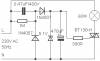
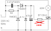
I want to turn on an AC bulb via a logic circuit to TRIAC. Before driving via logic circuit I checked the bulb directly from TRIAC.

The problem is the bulb is flickering.

*I need to turn on the bulb smoothly
*Also it must not be a problem if I swap the Live & Neutral lines

What changes do I have to do?
 

Attachments

  • Power.png
    Power.png
    3 KB · Views: 1,351
Last edited:
I can't find the datasheet for the H version of the BT138, but the datasheet for the BT138G states a trigger current range of 5-50ma when T2 is positive relative to T1. It has a trigger current range of 22-100ma when T2 is negative. So for it to be reliable, you'd need at least 100ma trigger current for ++ and +- quadrant firing. You have apx 11ma in your diagram.
EDIT: What are you making? If your logic circuit is connected to other devices or a human, then an Opto-isolator like saturn1bguy suggested is the way to go. You can get those with zero crossing built in.
 
Last edited:
Hi for both of you thanks.

I need to turn on the bulb for 30 mins & off.I removed the logic circuit because the bulb is flickering.So I removed the cct & checked but still its flickering.

Do I have to reduce the gate resistor?

That saturn1bguy's cct have lots of parts.

I want to stop this flicker thing with least amount of parts.
 
Last edited:
Hi saturn1bguy

That will be fine.

This is the final will it flicker?
 

Attachments

  • Power.png
    Power.png
    5.6 KB · Views: 800
I can't find the datasheet for the H version of the BT138, but the datasheet for the BT138G states a trigger current range of 5-50ma when T2 is positive relative to T1. It has a trigger current range of 22-100ma when T2 is negative. So for it to be reliable, you'd need at least 100ma trigger current for ++ and +- quadrant firing. You have apx 11ma in your diagram.
EDIT: What are you making? If your logic circuit is connected to other devices or a human, then an Opto-isolator like saturn1bguy suggested is the way to go. You can get those with zero crossing built in.

... just to name it: MOC3041
 
Right, that's good information, certainly. But for his purely resistive load the aformentioned random-phase triac is sufficient, just FYI.

firing a triac at random gurantees a good flicker 100%. Older household dimmers started flickering the lights at low settings because of non-synchronized triac firing. (At higher settings the flickering was still present, but barely visible.)

A good control circuit fires the triac for a lamp the way the glowing is only visible in absolute darkness - to full brightness without any flickering.
 
A good control circuit fires the triac for a lamp the way the glowing is only visible in absolute darkness - to full brightness without any flickering.

That's a good point, he was complaining about flicker, wasn't he :)

I had my head wrapped around zero-crossing+inductive loads and forgot the point that although his lamp is a resistive load potential side effects of random-phase firing could be visually discerned flicker - DOH!
 
That's a good point, he was complaining about flicker, wasn't he :)

I had my head wrapped around zero-crossing+inductive loads and forgot the point that although his lamp is a resistive load potential side effects of random-phase firing could be visually discerned flicker - DOH!

Here's an interesting test you can make firing a triac randomly with an inductive load (motor):

The first few cycles seem to be OK. Then the triac gets all messed up (may be dizzy :D) and fires at a sequence which reverses the motor very abruptly. (The motor doesn't know in which direction to rotate.)

If the triac can stand that torture the motor won't. :D

Here is a zero crossing unit with absolutely no phase shift (as it could be caused by a transformer)

The output can be used as a timing reference for an MCU to control pulse output length. (Timing output (10ms) based on 50Hz mains frequency, for 60Hz it will be 8.333~ms)

Boncuk
 

Attachments

  • ZERO-XING.gif
    ZERO-XING.gif
    11.6 KB · Views: 951
Last edited:
Hello guys I'm back.

Thanks for your comments.

I have to tell this I'm not going to dim the bulb.I need to turn on the TRIAC (bulb) after a preset time from my logic circuit.

I reduced the gate resister to 100R & the flicker thing was reduced a bit.After long time thinking I solved the problem.

The problem was in my logic circuit it draws more current because it has an LED.After adjusting the LED resister to higher value it was ok so the high voltage capacitor can supply enough current.

But Boncuk said it will still flicker even if I just turn on the triac at higher rate.What you mean?

Oh no do you need zero crossing circuits just to turn on TRIACs everytime?
 
Last edited:
Here's an interesting test you can make firing a triac randomly with an inductive load (motor)

I'm not sure of your point here, Boncuk. I think we already agree to use zero-crossing triacs for inductive loads, as I mentioned that above.

But because he was using a resistive load I had no initial problem with him using a random-phase triac driver, which view I subsequently revised to reduce light flicker, as you pointed out...
 
And guys please don't introduce opto isolates (MOCs) here because I need to drive it directly to TRIACs to minimize parts.

The flickering was gone now but like to hear some ideas.But some times the power supply doesn't work correctly.I think that capacitor charging discharging matters.So i have to remove & plug it back the 230AC cord many times.Thats very bad :(

saturn1bguy whats the software you using to draw above schematics?
 
Last edited:
OK guys I have a new question.

I planned to use TIC206 TRIAC.Can you please tell how to calculate the gate resister for this TRIAC?I attached the data sheet.

My circuit is 5V.
 

Attachments

  • tic206.pdf
    106 KB · Views: 396
Last edited:
I plan to use TIC206 TRIAC. Can you please tell how to calculate the gate resister for this TRIAC? My circuit is 5V.

This is a sensitive gate triac, and it looks like Igtmax is only 5mA for three quadrant operation, so 5V/5mA=1k.
 
This is a sensitive gate triac, and it looks like Igtmax is only 5mA for three quadrant operation, so 5V/5mA=1k.

Hi saturn1bguy thanks for the reply.

Oh my god yesterday I checked with a 100R resister.Worked well.

Your calculations showed the minimum resister is 1K.Soon I have to change that resister.Don't know whether it has burned or not........:(

I'm going to use 4.7K.
 
Status
Not open for further replies.

Latest threads

Back
Top