Continue to Site

Welcome to our site!

Electro Tech is an online community (with over 170,000 members) who enjoy talking about and building electronic circuits, projects and gadgets. To participate you need to register. Registration is free. Click here to register now.

  • Welcome to our site! Electro Tech is an online community (with over 170,000 members) who enjoy talking about and building electronic circuits, projects and gadgets. To participate you need to register. Registration is free. Click here to register now.

Transmitter with class-e amplifier attached not working

Status
Not open for further replies.
Ok, I went to here after searching for TV transmitters and found this URL: http://english.cxem.net/rf/rf37.php. It provided the following circuit:
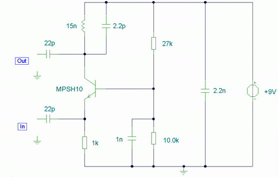
rf37-1.gif

I then made slight changes so I can apply my 20Khz source to it (I changed it after to 200Khz with no difference in results).

circuit.png

First I thought maybe this circuit is the best since it's in common-base configuration, but my screen doesn't show results. The green is the input waveform and the blue is output.
 
I went to here: **broken link removed**
and they say I can make a transmitter that transmits between 470 and 650Mhz with an almost-standard transmitter setup. It seems what they done was made the emitter resistor very high.

**broken link removed**
I wonder if that was my problem all along... insufficient resistance. When I tested it with mpsh10 transistor, I see mini modulation bubbles at the top of some input peaks but most of the time I saw a straight line. Now I think I need a better transistor.
 
Yes. You are so clever. The transmitter will work wonderfully with a 47k emitter resistor. Try it on 1v supply as well. It will work even better.
 
Status
Not open for further replies.

Latest threads

New Articles From Microcontroller Tips

Back
Top