Continue to Site

Welcome to our site!

Electro Tech is an online community (with over 170,000 members) who enjoy talking about and building electronic circuits, projects and gadgets. To participate you need to register. Registration is free. Click here to register now.

  • Welcome to our site! Electro Tech is an online community (with over 170,000 members) who enjoy talking about and building electronic circuits, projects and gadgets. To participate you need to register. Registration is free. Click here to register now.

Transistors

Status
Not open for further replies.

Frozenguy

Member
I get the basic idea of how transistors work but I need to actually apply a transistor as a switch in one of my circuits. Working with an NPN transistor like this guy: https://www.onsemi.com/pub/Collateral/BC846ALT1-D.PDF

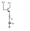
Base - 52 V (when a button is pressed, otherwise ground)
Collector - 24V
Emitter - LED load on button (integrated resistor).

Sound about right? This transistor should be good to handle all that. Base voltage can get up as high as 56 V.

Thanks for looking.
 
What current does your LED require? Note, if the base is at 52v then the emitter will be at 51.3v.

Mike.
 
What current does your LED require? Note, if the base is at 52v then the emitter will be at 51.3v.

Mike.

Not without a schematic.

Also, what is the input signal that it is over twice the system power supply voltage. Also, how much current can it supply into the circuit.

ak

Hi Mike and ak

Thanks for taking the time to respond. Here is my schematic. I am attempting to switch on that LED.
24 V will always be present. But I want the LED to switch ON only when 52 V is present. And off when 52 is not present.
 

Attachments

  • transistor.jpg
    transistor.jpg
    18.7 KB · Views: 156
The schematic tells all. The transistor is operating as an emitter follower, not a saturate switch. With 52 V on the base and 24 V on the collector, either the transistor or the LED will fail. Also, the LED operating current is dependent on the base voltage, the opposite of what you want.

I can't draw schematics on this machine, so here is a text description:

Emitter - to GND
Collector - to KED cathode
LED anode - to R1
R1 other end - to 24 V

For a standard small LED (Vf = 2 V - ish) and 20 mA LED current, R1 = 22 / 0.02 = 1.1K

Input - to R2 (base current limiting resistor)
R2 other end - Base

To calculate R2, you need the min and max voltage range when the 52 V is present. Also, you need to know the input voltage when the 52 V signal is off. If it is greater than about 0.2 V, then there is a risk that the transistor never turns off. There are simple ways around this if it is a problem.

ak
 
If theres a possibility of the 50 odd volt signal wandering around at only few volts, or changing from 0 to 50 odd very slowly the transistor will drop a lot of voltage generating plenty of heat.
So if your input signal does this either build a circuit that has schmitt trigger action, or a little simpler use a fat tranny that can take the abuse, something that has a heatsink tab, maybe one of the tip ranges.
A high value resistor to ground on the base would also stop the device from picking up noise and making the led flicker.
 
You didn't mention how much current the LED needs. Let's assume a standard small LED that requires 20 mA and drops 2 volts....

When the transistor is on (saturated), the emitter will be very near 24 volts. If the LED needs 20 mA and drops 2 volts, then the resistor in the emitter will need to be R = E/I = (24 - 2)/.02 = 1.1K. Use a 1.1K, 1W resistor.

Now, we need to add a resistor to the base drive. We need to provide current to the base to turn the transistor on, but we don't want to cram the entire 52 volts there. If we have 24 volts on the emitter (with the transistor on), then the base will need to be at about 24.6 volts. To fully saturate a BJT, rule of thumb is to provide the base with 1/10 the collector (and emitter) current. So we need 2 mA of base drive.

We have (52 - 24.6) volts of drop across the base resistor, and need it to provide 2 mA, so.. R = E/I = 27.4/.002 = 13.7K. I'd suggest adding a 15K, 1/4W resistor in series with the transistor's base.
 
Ok thank you for all the replies. The current for the LED is 10 mA. Here is the datasheet for the button/LED. It says 24 VDC illumination. part number : 82-6151.1154
https://eao.com/fileadmin/documents/PDFs/en/01_main-catalogue/EAO_MC_82_Main-Catalogue_EN.pdf


If theres a possibility of the 50 odd volt signal wandering around at only few volts, or changing from 0 to 50 odd very slowly the transistor will drop a lot of voltage generating plenty of heat.
So if your input signal does this either build a circuit that has schmitt trigger action, or a little simpler use a fat tranny that can take the abuse, something that has a heatsink tab, maybe one of the tip ranges.
A high value resistor to ground on the base would also stop the device from picking up noise and making the led flicker.
Ok great, thanks for the tip and heads up.

The schematic tells all. The transistor is operating as an emitter follower, not a saturate switch. With 52 V on the base and 24 V on the collector, either the transistor or the LED will fail. Also, the LED operating current is dependent on the base voltage, the opposite of what you want.

I can't draw schematics on this machine, so here is a text description:

Emitter - to GND
Collector - to KED cathode
LED anode - to R1
R1 other end - to 24 V

For a standard small LED (Vf = 2 V - ish) and 20 mA LED current, R1 = 22 / 0.02 = 1.1K

Input - to R2 (base current limiting resistor)
R2 other end - Base

To calculate R2, you need the min and max voltage range when the 52 V is present. Also, you need to know the input voltage when the 52 V signal is off. If it is greater than about 0.2 V, then there is a risk that the transistor never turns off. There are simple ways around this if it is a problem.

ak

Oh ok interesting. It will be from a battery pack so at any given moment, it wont vary much. But over all it can see 43 V-58 V. Nominally 48 V - 55 V.

You didn't mention how much current the LED needs. Let's assume a standard small LED that requires 20 mA and drops 2 volts....

When the transistor is on (saturated), the emitter will be very near 24 volts. If the LED needs 20 mA and drops 2 volts, then the resistor in the emitter will need to be R = E/I = (24 - 2)/.02 = 1.1K. Use a 1.1K, 1W resistor.

Now, we need to add a resistor to the base drive. We need to provide current to the base to turn the transistor on, but we don't want to cram the entire 52 volts there. If we have 24 volts on the emitter (with the transistor on), then the base will need to be at about 24.6 volts. To fully saturate a BJT, rule of thumb is to provide the base with 1/10 the collector (and emitter) current. So we need 2 mA of base drive.

We have (52 - 24.6) volts of drop across the base resistor, and need it to provide 2 mA, so.. R = E/I = 27.4/.002 = 13.7K. I'd suggest adding a 15K, 1/4W resistor in series with the transistor's base.
Thank you for that explanation. Helps bring the pieces together. The LED in the pushbutton needs 10 mA. I'm not sure what it drops however. The button says it works off 24 VDC illumination and there are 12 VDC and 6 VDC illumination options. But I am currently using the 24 V option because I have 24 V on the board always. Well, its half tap of the battery pack so it goes from 24 - 27.5.
 
If you change it so the LED is in the collector circuit then the base will need 1 to 2mA. With 50v you will need a base resistor of 2.5k to 5k.

Mike.
 
Is there anything against using the 50 some odd volts to drive the LED directly through a 4.7k resistor and emilinate the need for using a transistor? .... 50V/4.7k = aprox 10mA
 
Whoops, my base resistor calcs were out, as Baeu points out they are 10 times too small. Agree about no need for transistor.

Mike.
 
If you can spare 10 mA from the 52 volts source, then driving the LED directly is the simplest way to go. You will need to add an external R = E/I = (52 - 24)/.01 = 2.8K (use 2.7K 1/2 watt).

If you still want to use that transistor, then: Since the lamp assembly is rated at 24 volts, that means the resistor is built in and you do not need to add a series resistor for the LED. The transistor collector/emitter current will be 10 mA, so the base only needs about 1 mA. If you go with the LED in the collector and the transistor emitter grounded, then the needed base resistor will be 50K (use 47K or 51K). If you want the LED in the emitter, then the transistor base resistor will need to be 27K.
 
Ok thank you for the suggestions. The original reason I went to a transistor and 24v was because the power dissipation looked like it was getting out of hand. But perhaps it's not.

I calculate I will need the set of resistors to dissipate as much as 0.539 W. The voltage could be as high as 56 V topped off to the top. 56-2.1V = 53.9 V
53.9 V * 0.01 A = 0.54 W.

With that said, I'm assuming the integrated resistor is about 2.19 kohm. If I add another resistor to compensate for the increase voltage drop, it shouldn't mess with the drop across the integrated resistor too much if I size it correctly right? I calculated the entire drop, then subtracted the integrated resistance and came up with a value of 3.2 kohm. Closest I can find is a 3.3 kohm in 3/4 W in a 1206 package from Vishay: https://www.digikey.com/product-detail/en/vishay-dale/RCL06123K30FKEA/541-2372-1-ND/5270371

The new resistor will have to dissipate 0.33 W of power. Will a 1/2 resistor be enough head room? This button will not be pressed often. And when it is pressed, will only be held down for maybe upwards of 5 seconds. Very stable DC voltage.
 
Remember that there is 24 volts dropped across the LED assembly, so that leaves you with only (56 - 24 =) 32 volts to drop across your added resistor.

P = E²/R = 32²/3300 = 0.31 W. Your 3.3K 3/4W selection should be fine.
 
Remember that there is 24 volts dropped across the LED assembly, so that leaves you with only (56 - 24 =) 32 volts to drop across your added resistor.

P = E²/R = 32²/3300 = 0.31 W. Your 3.3K 3/4W selection should be fine.

I edited my post as you were typing, but thank you for catching that.

Thank you everyone for the help and piecing together my limited understanding of the uses of transistors.
 
Status
Not open for further replies.

Latest threads

New Articles From Microcontroller Tips

Back
Top