Continue to Site

Welcome to our site!

Electro Tech is an online community (with over 170,000 members) who enjoy talking about and building electronic circuits, projects and gadgets. To participate you need to register. Registration is free. Click here to register now.

  • Welcome to our site! Electro Tech is an online community (with over 170,000 members) who enjoy talking about and building electronic circuits, projects and gadgets. To participate you need to register. Registration is free. Click here to register now.
Status
Not open for further replies.

BManriquez

New Member
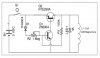
I'm trying to make a magnetic pendulum circuit for a holiday decoration, and I need some help. I found this circuit online (see attached JPG), but the circuit behavior is not consistent and it rarely works correctly. Most of the time, the coil is ALWAYS on (rather than momentarily on when the magnet passes over) which brings everything to a stop. How is this circuit supposed to work? Since the base of Q1 is always tied to the 3V source through the 1M resistor, won't that always keep the transistor on - which is what is currently happening. I don't understand why the base of Q1 needs to be tied high all the time - wouldn't the impulse from the coil trigger Q1 on it's own? I guess I've never seen a transistor tied partially high - I've always used them where the base is either tied high (+V) or not (0V). I just don't understand the function here.
Is there a better way to accomplish this task? I've tried using IR sensors to trigger Q1 instead, but I couldn't get the timing right. Does anyone have a better, more consistent way to produce a magnetic pendulum? I have spent so many hours trying to get this thing to work, and it's brought me nothing but problems. Any help or information will be greatly appreciated. Thanks!
 

Attachments

  • PendulumCircuit.jpg
    PendulumCircuit.jpg
    24.1 KB · Views: 287
Looking at that circuit, I'd guess the pot should be set so there is just under 0.6V on the base of the transistor when the conditions are static.
As the magnet swings over the coil a voltage should be induced which will increase the base voltage and trigger a pulse.

It's not a good circuit. I'd add a resistor in the base connection to the upper transistor, to start with.


I'd also try different orientations for the coil and magnet, it may be quite critical for the timing and polarity of the induced trigger and coil attraction or repulsion.


A very old pendulum device my brother once owned had a bar magnet attached to the centre of a long curved wire which formed the bottom of the pendulum - imagine a sixth of a circle outline with a curve and two radials made of wire, with the junction of the radials attached to the pendum swivel axle.

There was a tubular coil fixed to the frame, so the magnet was inside it at the centre position. The coil polarity was arranged to repel the magnet.

The "control" was just a thin springy wire from an insulated terminal on the frame and a metal blade or flag protruding from an attachment between the two radials.

There was a 1.5V D cell clipped in the base of the device. Each time the pendulum swung to the centre position the blade/flag touched the spring wire and stayed in contact with that for a very short distance, until it slipped past. That meant the coil always a pulse biassed to when the magnet was just past centre and the repulsion boosted the pendulum swing.


Edit - have a look at the circuits near the bottom of this page, they seem rather better than the one you found:
 
Last edited:
Status
Not open for further replies.

Latest threads

New Articles From Microcontroller Tips

Back
Top