Continue to Site

Welcome to our site!

Electro Tech is an online community (with over 170,000 members) who enjoy talking about and building electronic circuits, projects and gadgets. To participate you need to register. Registration is free. Click here to register now.

  • Welcome to our site! Electro Tech is an online community (with over 170,000 members) who enjoy talking about and building electronic circuits, projects and gadgets. To participate you need to register. Registration is free. Click here to register now.

Transistorrrr !!????? Help

Status
Not open for further replies.

sudar_dhoni

New Member
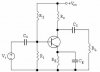
i have a basic doubt in the figure that i have posted

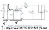
NOTE THE WORD CURRENT MENTIONED BY ME IS ELECTRON FLOW AND NOT CONVENTIONAL

in the figure how does the potentiometer vary the voltage
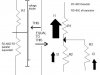
If u use potentiometer u can vary the voltage drops.This is valid only if u draw current from the battery
but for transistor only the battery's electric field is used there
i cant understand how a potentiometer can vary the electric field of the battery acting on the transistor.
i know how potentiometer works i learnt from this site

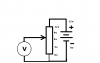
but thats valid only in the figure that i have posted which has rheostat and voltmeter

but in the transistor figure the current from the negative terminal flows directly to the emitter and does not flow through the rheostat
then in that case how can the potential be varied because the electrons from the negative terminal are not at all flowing through the rheostat
 

Attachments

  • Transistor currents 4.PNG
    Transistor currents 4.PNG
    16.1 KB · Views: 118
  • MOKKA.jpeg
    MOKKA.jpeg
    53.7 KB · Views: 130
but in the transistor figure the current from the negative terminal flows directly to the emitter and does not flow through the rheostat

Yes current does flow through the rheotat.
You have over simplified things.
See my modified version of your diagram, I1 = I2 + I3

JimB
 

Attachments

  • Currents.JPG
    Currents.JPG
    38.5 KB · Views: 128
Yes current does flow through the rheotat.
You have over simplified things.
See my modified version of your diagram, I1 = I2 + I3

JimB

according to ur figure how does the rheostat vary the voltage of the electrons which are going to the emitter
1) voltage of electrons (energy of electrons) going to the emitter does not drop at all according to ur figure but the function of that rheostat is to drop the voltage
then what is the function of the rheostat there.

2)also where will that I2 end up after it passes through the rheostat

3)can u explain the entire functioning of common emitter transistor in terms of electron movement

also can u explain my doubt in transistor amplifier i have given the link
https://www.electro-tech-online.com/threads/transistor-amplifier-help.100696/
 
according to ur figure how does the rheostat vary the voltage of the electrons which are going to the emitter
1) voltage of electrons (energy of electrons) going to the emitter does not drop at all according to ur figure but the function of that rheostat is to drop the voltage
then what is the function of the rheostat there.
The rheotat DOES DROP THE VOLTAGE. Get a proper understanding of simple resistive voltage dividers before trying to understand transistors.
2)also where will that I2 end up after it passes through the rheostat
It combines with I3 and flows back to the battery as I1.
3)can u explain the entire functioning of common emitter transistor in terms of electron movement
No, this is standard work. Google it.
also can u explain my doubt in transistor amplifier i have given the link
https://www.electro-tech-online.com/threads/transistor-amplifier-help.100696/
No.
 
when the pot is turned up so its output voltage is 0.6v then the base-emitter of the transistor is forward-biased and begins to conduct current. If the pot is turned up more then the base current increases but the base voltage barely becomes higher than about 0.7V.

The current gain of the transistor causes a collector to emitter current that is a few hundred times higher than the base current.
 
potential divider is really easy to understand, it is same as mixing a bright color with a dark color to very the brightness of the output. a potentiometer consists of one long restor divided into two parts with a moovable wiper. this also goes for potetial divider. one thing is certain, one resistor touches vcc (high) and the other Gnd. the middle (wiper) shuld go out
 
The rheotat DOES DROP THE VOLTAGE. Get a proper understanding of simple resistive voltage dividers before trying to understand transistors.

It combines with I3 and flows back to the battery as I1.

No, this is standard work. Google it.
No.

u r telling it combines with I3 and goes back to the battery
then where do u vary the voltage between emitter and base using rheostat
because only the current I3 is going to the emitter and its voltage is not varied as it does not flow through the rheostat which means the base emitter voltage is also not varied
 
Last edited:
Why do you insist that I3 does not flow through the rheostat? This is a parallel circuit, I2+I3=I1. I2 flows through the entire rheostat filament, while I3 flows only through the wiper and the half of the rheostat which is isolated by the wiper. yet, they both recombine at the rheostat to form one current. This would be like a river flowing, and split by an island, only to recombine on the other side.

Maybe the following picture will help, by eliminating the transistor and rheostat and replacing with equivelant resistances.
 

Attachments

  • transistor.jpg
    transistor.jpg
    21.2 KB · Views: 114
Last edited:
when the pot is turned up so its output voltage is 0.6v then the base-emitter of the transistor is forward-biased and begins to conduct current. If the pot is turned up more then the base current increases but the base voltage barely becomes higher than about 0.7V.

The current gain of the transistor causes a collector to emitter current that is a few hundred times higher than the base current.

'audioguru genius'
now u have given me some energy
what u r saying is that the rheostat is used to vary the base current
as the base current increases which means automatically the base emitter voltage must have increased due to which a larger no of electrons is now coming out of the base. i.e it gives an indirect meaning of varying the base emitter voltage by varying the base current.
it is the converse of Ohm's law(as voltage increases current increases)
i.e as current increases it means that voltage must have increased.
the same is applied here am i right????

A couple of posts back I took the time to draw an illustration of how the currents and voltages relate between the rheostat and base-emitter of the transistor. It is very explanatory. I think you are on the right track but please take the time to understand my illustration.
 
A couple of posts back I took the time to draw an illustration of how the currents and voltages relate between the rheostat and base-emitter of the transistor. It is very explanatory. I think you are on the right track but please take the time to understand my illustration.

my problem is not what u think of
my problem is that the electrons I3 go through the rheostat only at the end(after passing through the transistor) then how does rheostat vary the voltage of base emitter
now i understood from the audio guru's post
what u said i knew that earlier
i wanted to know how the rheostat functions in varying the base emitter voltage as the I3 first goes to base emitter and then only through the rheostat if I3 first goes to the rheostat then only the rheostat can vary the voltage since the I3 goes only at the end
i had a doubt of how it varies the base emitter voltage
now its clear
thanks for ur hardwork
:)
 
Last edited:
What you are saying is that the rheostat is used to vary the base current.
As the base current increases which means automatically the base emitter voltage must have increased due to which a larger no of electrons is now coming out of the base.
Not really.
The base-emitter junction is a diode, not a resistor. The voltage might increase from 0.65V to 0.68V when the current is increased a lot.
 
Not really.
The base-emitter junction is a diode, not a resistor. The voltage might increase from 0.65V to 0.68V when the current is increased a lot.

its not actually ohm's law but somewhat close to it right
ok i understood that

can u plz explain me the priciple behind amplifier
that what gets amplified and how does it get amplified
i want explanation in terms of what is happening inside a transistor such as electron and hole movement. i want it for the CE configuration
 

Attachments

  • image624.jpg
    image624.jpg
    11 KB · Views: 109
We do not talk about electrons and holes when we describe how a transistor amplifies. Electrons and holes describe the transistor without a signal (its bias currents).

the transistor has an input and an outpout coupling capacitors so it amplifies AC, not DC.
The emitter has a capacitor bypassing the emitter resistor so the transistor has an AC voltage gain that is RC and RL in parallel divided by its internal emitter resistance that is 0.026 divided by its collector current.
This transistor circuit has a fairly low input impedance so it must be driven by a low impedance for low loss.

The input signal changes the base-emitter voltage slightly that changes the base current a little. The collector current changes much more which is amplification.

i have many doubts in that circuit diagram
1) why do we use RE
my sir told its used for stabilisation
what is stabilisation

2)why do we use capacitor CE and CC
my sir told its used for coupling
what is coupling

3)one small request plz can u mark the direction of current in the diagram
it would be better if u mark the direction of electron flow

4) u mentioned
The input signal changes the base-emitter voltage slightly that changes the base current a little. The collector current changes much more which is amplification

i know a little about the electron movement in the amplification process plz verify it
electrons from N(emitter) go to P(base) some of the electrons recombine with holes and the rest goes to the collector(N)
since some electrons have recombined with holes in the base the base which was earlier neutral now is -vely charged.therefore it blocks the emitter current now
once the base voltage is increased the electrons that have recombined would get attracted and flow to the +terminal of VBB now the base can allow the emitter current
as the base voltage is slowly increased more of electrons in the base are attracted therby offering no resistance to the emitter and majority can now go the collector
i understood this but i have one doubt
emitter current=base current + colllector current
IE=IB + IC
if IB increases then IC should decrease
how come both increase
also electrons from emitter only split up into base current and collector current if base current increases i.e if more electrons go to the base then the electrons going to the collector has decreased
then how come we say that as base current increase collector current increases
the word current here refers to motion of electrons not conventional

p.s i am quite inquisitive in electroncis and electrical
i going to enter engineering so i want to learn all the basic concepts so that it will help me and that i can teach others
if u find me irritating plz tell me i wont disturb u:eek:
 
my problem is not what u think of
my problem is that the electrons I3 go through the rheostat only at the end(after passing through the transistor) then how does rheostat vary the voltage of base emitter

:)

If you already understood my illustration, then you already understood the answer to this question.

Look at the drawing on the left. Consider that the rheostat, when divided by the "wiper", becomes essentially two resistors.

Then consider the wiper is connected to the B-E of the transistor, so that the resistance of B-E is parallel to the resistance of the bottom half of the rheostat. You know that resistors in parallel can be treated as one resistor.

So, refer to the illustration on the left. You have a voltage divider.

So, if you move the rheostat wiper and change the voltage, you understand that two voltage drops add to be TOTAL VOLTAGE in a series circuit.

So, a change in the rheostat voltage will set up a voltage drop change in the B-E.

My illustration describes everything you ask. Use your analytical reasoning abilities to understand.
 
Last edited:
If you already understood my illustration, then you already understood the answer to this question.

Look at the drawing on the left. Consider that the rheostat, when divided by the "wiper", becomes essentially two resistors.

Then consider the wiper is connected to the B-E of the transistor, so that the resistance of B-E is parallel to the resistance of the bottom half of the rheostat. You know that resistors in parallel can be treated as one resistor.

So, refer to the illustration on the left. You have a voltage divider.

So, if you move the rheostat wiper and change the voltage, you understand that two voltage drops add to be TOTAL VOLTAGE in a series circuit.

So, a change in the rheostat voltage will set up a voltage drop change in the B-E.

My illustration describes everything you ask. Use your analytical reasoning abilities to understand.

i understand ur explanation but this is valid only if u consider R2 and R3 together
if u consider them separately u can explain this am i right
i.e the voltage divider diagram can only explain my doubt and not the one on ur right
 
i understand ur explanation but this is valid only if u consider R2 and R3 together
if u consider them separately u can explain this am i right
i.e the voltage divider diagram can only explain my doubt and not the one on ur right

No, it is the SAME.
It explains it the SAME. Please consider that the bottom of the rheostat joins with B-E to become a parallel resistance.

As the voltage drop in the top half of the rheostat is varied, so will the voltage drop across B-E+bottom of rheostat(parallel)...IN A CONVERSE MANNER.
 
No, it is the SAME.
It explains it the SAME. Please consider that the bottom of the rheostat joins with B-E to become a parallel resistance.

As the voltage drop in the top half of the rheostat is varied, so will the voltage drop across B-E+bottom of rheostat(parallel)...IN A CONVERSE MANNER.

superb i understood it now fully thanks for ur patience ke5frf
ur last post gave me the answer to my doubt THANKS
could u plz explain my doubt in the amplifier which i have posted in this same thread
:)
 
Status
Not open for further replies.

Latest threads

New Articles From Microcontroller Tips

Back
Top