Continue to Site

Welcome to our site!

Electro Tech is an online community (with over 170,000 members) who enjoy talking about and building electronic circuits, projects and gadgets. To participate you need to register. Registration is free. Click here to register now.

  • Welcome to our site! Electro Tech is an online community (with over 170,000 members) who enjoy talking about and building electronic circuits, projects and gadgets. To participate you need to register. Registration is free. Click here to register now.

Transistor(s) as an off switch?

Status
Not open for further replies.

thepaan

Member
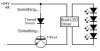
I'm trying to design a circuit to power some LEDs with a diode as a temperature sensor. I want the circuit to turn off the LEDs when it gets too hot. The diode forward voltage will rise as the temperature rises which I can use with a transistor to turn something on, but I want to turn it off. I figured out how to set it up with a transistor and a relay but I'd like to stick to only transistors. Is there a way to use a transistor as an off switch instead of an on switch?
 
I am only just learning again but a jfet is equivelent to an "off" switch in transistors.

Not sure if this helps or not....
 
I am only just learning again but a jfet is equivelent to an "off" switch in transistors.

Not sure if this helps or not....

A J-Fet is a 'normally-on' transistor. (the normal 'BJT' transistor is 'normally-off')

With a BJT you give it a small positive current and it switches on.

With J-FET, you give it a negative voltage and it switches off.
 
A J-Fet is a 'normally-on' transistor. (the normal 'BJT' transistor is 'normally-off')

With a BJT you give it a small positive current and it switches on.

With J-FET, you give it a negative voltage and it switches off.
Just to clarify, those polarities are for an NPN BJT and an N-Channel J-FET. The current direction and voltage are opposite for a PNP BJT and a P-Channel J-FET.
 
The diode forward voltage will rise as the temperature rises which I can use with a transistor
No.
The forward voltage across a diode drops as its temperature rises.
The base-emitter voltage of a transistor does the same and the transistor amplifies the voltage change.

The transistor turns on more when it gets warm. It can turn off another transistor.
 
I read a little bit about JFETs and that seems like it will work but I don't think I can use negative voltage. I'm looking at MOSFETs right now to see if those will work (a JFET is a type of MOSFET?) but my brain is starting to hurt :p

Sorry if this is all too basic but I haven't done anything like this since I got my mom to buy me a beginner electronics kit in elementary school.

Anyways this is what I have with the relay plus transistor. I still need to limit the current to the temperature diode but that's later.... I can use another LED driver for it as a last resort.
 

Attachments

  • LEDcircuit.JPG
    LEDcircuit.JPG
    18.4 KB · Views: 666
A diode can be used in the configuration shown in the circuit (not as shown in the picture, but reverse-biased so leakage increases with temperature), it would work, but it's difficult to predict. You probably do a lot better with a thermistor instead as temperature sensor.
 
Last edited:
I read a little bit about JFETs and that seems like it will work but I don't think I can use negative voltage. I'm looking at MOSFETs right now to see if those will work (a JFET is a type of MOSFET?) but my brain is starting to hurt :p

Sorry if this is all too basic but I haven't done anything like this since I got my mom to buy me a beginner electronics kit in elementary school.

Anyways this is what I have with the relay plus transistor. I still need to limit the current to the temperature diode but that's later.... I can use another LED driver for it as a last resort.
Your relay shorts your power supply in the NO position.
 
Last edited:
I think these posts are comming in a little faster than I am reading them :p Let me explain the situation a little more. I purchased a heatsink from an online retailer and after delivery, upon inspection, I discovered an unknown - presumably - thermal sensor embedded in the base. I figured I might as well use it since it is already there. After some multimeter testing I have decided it is a silicone diode.

No.
The forward voltage across a diode drops as its temperature rises.
The base-emitter voltage of a transistor does the same and the transistor amplifies the voltage change.

The transistor turns on more when it gets warm. It can turn off another transistor.

My diode at room temperature (yesterday was hot so about 28*C) had a forward voltage drop of .66V. Generically this device should have a linear change of 2.3 mV/°C. If the voltage is down instead of up then at say 100*C, it should have a forward voltage drop of .495V. In this case could I flip the transistor and use one such that when the voltage drops below .495 it shorts the LED circuit?
 

Attachments

  • LEDcircuit2.JPG
    LEDcircuit2.JPG
    14 KB · Views: 372
I'm looking at MOSFETs right now to see if those will work (a JFET is a type of MOSFET?) but my brain is starting to hurt :p
JFETs (Junction FET) and MOSFETS (Metal Oxide Semiconductor FET) both are a type of FET (Field Effect Transistor)
 
If I am reading the spec sheet correctly for the TIP41A, then I need at least 1.5V going to the base otherwise V(CE) will not be open all the way. So, I need to amplify the voltage from the diode to the TIP41A with another transistor? I revised my drawing again too. You guys have helped a lot so far. :p
 

Attachments

  • LEDcircuit2.JPG
    LEDcircuit2.JPG
    14.2 KB · Views: 265
Many buck LED drivers have an enable or shutdown pin. You may not have to switch the entire chip.
You really need a comparator like an LM393 for your temperature switching. You can adjust the temperature set point with a pot, and you can add some hysteresis so it doesn't "chatter" at the threshold.
 
Last edited:
I'm not too worried about accuracy so I think the embedded diode is fine. For example, the max operating temp for the device is 150*C. If the diode can turn off the lights at 120 +/- 20*C or so then I'm fine with that.

Many buck LED drivers have an enable or shutdown pin.

Do you mean like the LuxDrive 3021 - it has a ctrl and ref pin. From the datasheet:

https://www.leddynamics.com/LuxDrive/datasheets/3021-BuckPuck.pdf

Where a manual on/off control is desired, the potentiometer in figures 9 and 10 may be replaced by a pushbutton or toggle switch. The output current will be zero when the switch is closed.

I'm back to the first problem if I hook the diode to voltage and a transistor to the diode, ref and ctrl. The switch will be in the opposite position of what I want.
 
Use a comparator, e.g. the LM393 or LM311, to compare the voltage across the diode with a stable voltage reference.

Here's a good comparator tutorial.
**broken link removed**
 
Thanks for the info about the comparator. I may have some questions on that later.

I tested this thermal whatever on a different multimeter at work this morning. This one has a temperature dial setting. From what I have read a thermocouple should be attached to this. The multimeter + thermalwhatever reads 23.4*C where the AC unit (whole degrees only) reads 24*C which seems fairly accurate.

Does that setting only work for thermocouples? If not, will I get erroneous readings if it is some other kind of semiconductor at other temperatures... lets say, if I put it in the freezer? Furthermore how does the multimeter know what kind of voltage to expect from the thermocouple?
 
Right, a thermocouple will read a higher temperature on the multimeter the more voltage it passes. An RTD (if it is possible to connect to a multimeter and still get a reading for temp) will behave in the opposite fashion as resistance is increased with temp.

So, can you get a reading from a multimeter with anything or must it be a thermocouple?

Anyways, I put the heatsink in the freezer during lunch and now it doesn't read anything. I accidently touched the two wands together and noticed the multimeter still reads room temperature. Anyone know why that is?
 
Do you have a thermister or a thermocouple ?

The 2 are quite diffferent - If it is a thermocouple you have it is probably K type this is the most common type to read on a multimeter. Thermocouples should be connected with the correct rating wires otherwise they wont operate properly.

Multimeters that can read other types of thermocouple have to be set to the right type to read correctly.

All the thermocouple types are listed in the article linked in Roff's post above some are for specialized applications so you may only see 2-3 around.
 
Last edited:
Status
Not open for further replies.

Latest threads

New Articles From Microcontroller Tips

Back
Top