Continue to Site

Welcome to our site!

Electro Tech is an online community (with over 170,000 members) who enjoy talking about and building electronic circuits, projects and gadgets. To participate you need to register. Registration is free. Click here to register now.

  • Welcome to our site! Electro Tech is an online community (with over 170,000 members) who enjoy talking about and building electronic circuits, projects and gadgets. To participate you need to register. Registration is free. Click here to register now.

Touch Switch for LED's

Status
Not open for further replies.

tjones27

New Member
Hi,
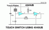
im trying to create a touch sensitive switch for my University project, but im not that great at electronics. i have found a diagram of one that i would like to use, but have become stuck as i was told that i needed a buffer? more specific i needed to pass the output of the 4049 to an amplifier as the output of the 4049 cannot be connected to any LED's? sadly this does not mean much to me. what amplifier should i use, and how would i connect it??any advice would be greatly appreciated. and im trying to do it so that one touch of the pad turns the lights on, and then touch it again to turn it off. im going to be using a 12V power supply.
the diagram is hopefully attached. also which is positive and negative?? im guessing the top is +ve and the bottom -ve? if somebody could complete the rest of the diagram for me, or help me to do so that would be fantastic!

many thanks

Tj
 

Attachments

  • touch-switch-4049.gif
    touch-switch-4049.gif
    3.7 KB · Views: 2,155
The 4049 has 6 inverters. The touch switch circuit uses only two of them so you can use the remaining 4 inverters as buffers or parallel them for more output current.
You must use ALL the inverters or properly disable unused ones.

The datasheet does not show it but Vcc pin 1 is the positive supply pin and Vss pin 8 is the negative of the circuit.

I would be afraid that static electricity from your finger in winter will destroy the 1nF capacitor and the 4049 IC.
 
Hi, thanks for the reply.
would there be any other way around it to stop that from happening in the winter?
by the sounds of it, it would be easier to use all of the inverters as that would also work as a buffer(if thats correct?) how would i do this?

sorry this is my first time using anything other than wire, a simple on-off switch, batteries and some form of LED. not that i am an idiot, but if you could explain it to me as if i am, i might be able to understand it ;)

Regards
 
A static electricity spark is 10,000V or more. A series resistor will not help because it will arc with only about 250V.
You can protect the circuit from static electricity by adding resistors and diodes and/or zener diodes to the inputs.

Each unused inverter in the CD4049 (that has 6 inverters) can be disabled by connecting its input to 0V or the positive supply voltage.
When inverters are used as an output buffer then they can be connected in parallel (inputs connected together and outputs connected together) then their output current is multiplied.
 
If all you're trying to do is switch an LED, a much simpler solution would be a 555 timer. A simple circuit is shown below.

**broken link removed**

I've used that one on several occasions and it works fairly well. However, it may be a good idea to add a pull-up resistor, as it's is extremely sensitive to RF. Never had a problem with static electricity, though.

That design simply turns on for a set amount of time and then shuts off. If you want a bistable version (stays on until you manually reset it), here's one I drew up a while ago:

bistable_touch_switch.JPG

Hope this helps!
Regards,
Der Strom

P.S. Sorry for the weird image sizes :p
 
Last edited:
use 555 to make a pulse and use a 4017 to make on and off by touching the same pad....

Yep, I've seen that done as well. I've also seen the 555 connected to a 7474 flip-flop. Either should work.
 
Status
Not open for further replies.

Latest threads

New Articles From Microcontroller Tips

Back
Top