RAJ KUMAR MUKHERJI
New Member
Hello,
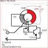
I have seen numerous Youtube videos on super high voltage Joule Thief projects. They are using small one inch ferrite toroids and from single 1.5 volt AA battery power a 3-5 watt 110-220 volt cree LED brightly consuming merely 200 mA of current from the battery! The following link will help you understand it better:
https://www.instructables.com/id/Make-a-SUPER-Joule-Thief-Light/
However, all such similar links do not specify the specific inductance of the Toroid being used or the Permeability. All they suggest is to use high permeability ferrite toroid! The authors also do not provide the answer.
Now, I want to replicate such a project at low cost. For that purpose, I have procured the following Toroids from Element14 (India):
Therefore, I will be more than happy if you can guide me accordingly on this.
Thank you,
With best regards,
Raj Mukherji
I have seen numerous Youtube videos on super high voltage Joule Thief projects. They are using small one inch ferrite toroids and from single 1.5 volt AA battery power a 3-5 watt 110-220 volt cree LED brightly consuming merely 200 mA of current from the battery! The following link will help you understand it better:
https://www.instructables.com/id/Make-a-SUPER-Joule-Thief-Light/
However, all such similar links do not specify the specific inductance of the Toroid being used or the Permeability. All they suggest is to use high permeability ferrite toroid! The authors also do not provide the answer.
Now, I want to replicate such a project at low cost. For that purpose, I have procured the following Toroids from Element14 (India):
- Manufacturer: FAIR-RITE; Ferrite Toroid: 25.4mm x 15.5mm x 12.7mm; Core Material Grade: 77; AL (nH) : 2700 ±25% (I have procured)
- Manufacturer: FERROXCUBE; TN25x15x10; Core Material: 3E25; AL: 5.62µH (I have procured)
- Manufacturer: EPCOS; Toroid; 25.3 × 14.8 × 10.0; Core Material Grade: T37; AL (nH): 6970 ±25% (yet to procure based on your advice)
Therefore, I will be more than happy if you can guide me accordingly on this.
Thank you,
With best regards,
Raj Mukherji


")