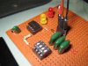
I have soldered up a 555 test circuit not unlike the one I've linked to here to use as both a 555 tester and a reusable square wave oscillator.
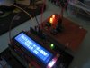
I don't have an oscilloscope at the moment and my frequency testing is done using a microcontroller used as a frequency counter like this one that i've linked to.
I initially wired the test circuit up on a breadboard to test the frequency counter which seemed to be malfunctioning after having previously worked flawlessly.
When I switched the TLC555CP for a NE555 it worked so I assumed that the TLC555CP was damaged.
Realising that this was a handy circuit I soldered it up on a prototype board and when using it initially I didn't have the frequency counter connected.
It worked fine with the NE555 flashing the LED's properly and I thought i'd give the TLC another go in the soldered circuit and it seemed to work which really surprised me.
But as soon as I connected the frequency counter it stopped working.
My initial guess that this is related to the low power claim for the TLC555CP although I wouldn't have expected the frequency counter to be influencing it.
My initial thought is that I need to buffer the output using an inverter like a 7404 or 7414 or even just running it into a transistor but I thought I should check if this isn't just an issue of needing the right circuit on the output with pull ups or pull downs or whatever.
When it comes to understanding what needs pull ups or pull downs I really am at a loss so any help would be appreciated in respect to their use in this circuit and how I should go about ensuring that the frequency meter (or any other circuit) will function when connected to the output.
All this came about because I was trying to test the frequency of the VCO output of a 4046 PLL and was getting nothing on the frequency counter so I assume that the VCO output and the TLC555CP output must be very similar in their characteristics.
 mostly in problem solving and testing though
")