Continue to Site

Welcome to our site!

Electro Tech is an online community (with over 170,000 members) who enjoy talking about and building electronic circuits, projects and gadgets. To participate you need to register. Registration is free. Click here to register now.

  • Welcome to our site! Electro Tech is an online community (with over 170,000 members) who enjoy talking about and building electronic circuits, projects and gadgets. To participate you need to register. Registration is free. Click here to register now.

Working with tlc555cp problem

Status
Not open for further replies.

kinarfi

Well-Known Member
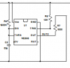
I am thinking of making the attached circuit for my off road vehicle and I was testing it in stages as I went, and I found that the circuit wouldn't trigger consistently and I would have to disconnect power to get it working again and and if I grounded the rst, it wouldn't trigger afterwards, then, after a while of playing with it, I think I fried it, so I turned every thing off, turned out the lights and went to watch TV. Any one have any ideas what's happening or what I doing wrong. power was 13 vdc, R4 = 1meg, C2 was 47uf, then 35uf, then 10uf and 1uf. The 1M and 47uf ran for about 5 minutes, If I remember right. the switch for the trigger was touching a wire to ground.
Kinarfi
Another problem I was having was in Spice, I had to NOT hook up the resets or it would hang as soon as either reset was grounded.
 

Attachments

  • Untitled.png
    Untitled.png
    21.2 KB · Views: 247
  • Blinkers2.asc
    7.4 KB · Views: 172
  • Untitled.png
    Untitled.png
    4.3 KB · Views: 245
Last edited:
... I had to NOT hook up the resets or it would hang as soon as either reset was grounded.

That is because RESET dominates over the other functions. RESET must be tied to VCC for normal operation.

It should really be called RESET~ (RESET LOW).
 
Last edited:
You have the pins backwards.
The reset pin must be high for the 555 to work. When the reset pin is low then the 555 resets.
 

Attachments

  • 555 pins.PNG
    555 pins.PNG
    9.3 KB · Views: 913
You have the pins backwards.
The reset pin must be high for the 555 to work. When the reset pin is low then the 555 resets.

Sorry about that, I drew up on side(left signal), then copied and mirrored for the right side, then when I printed it to build off of, I copied and printed the right side. Confused me also as I built circuit.
Thanks to both of you for you help.
Kinarfi
PS, added 100 ohm pull up resistors to the reset circuit and it worked on spice and will probably work on the bench, then in the vehicle. Thanks again.
 
Last edited:
I use about 10K for the pull-up on RESET or TRIG, if needed. Wastes less power than 100Ω would...
 
Things seem to being going well, I don't think there is any problem with how this is going to work, but I thought I would get other's opinions. Attached is the design for one side of the blinkers, the power to the signal originally went from + , thru a fuse, to the scintillator, to the left, off, right switch to the light to ground. I'm replacing the switch (red circle) with 2 P Fets (other red circle) controlled by 555s via and inverting transistors. My question is: if a P Fet is biased on and you remove power from the source and leave it biased on, is there any danger of damaging the Fet? I think "NO", Correct?
Thanks,
Kinarfi
 

Attachments

  • Untitled.png
    Untitled.png
    61.4 KB · Views: 211
Status
Not open for further replies.

Latest threads

Back
Top