Continue to Site

Welcome to our site!

Electro Tech is an online community (with over 170,000 members) who enjoy talking about and building electronic circuits, projects and gadgets. To participate you need to register. Registration is free. Click here to register now.

  • Welcome to our site! Electro Tech is an online community (with over 170,000 members) who enjoy talking about and building electronic circuits, projects and gadgets. To participate you need to register. Registration is free. Click here to register now.

Timed 'Double-Click' switch detector circuit ?

Status
Not open for further replies.
In the meantime, I'm going to pop a post in the PIC section re the possibility of someone being able to help draft a few lines of code for a 12C509 etc.

I read your post in the PIC section -- either a slightly different project, or the spec has moved on a little bit?:)

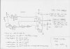
If you think of what you are trying to do slightly differently, I reckon you could do it with just two CMOS ics.

Instead of looking for two switch presses within a fixed time window, why not have the 'B' led output controlled by a single much longer switch press?

So - every time you press the switch, it fires a 1 second monostable (output 'A'). If you want output 'B' to activate, press and hold the switch for say 1 second -or more? Just select the delay time constant to suit.
Subsequent 'quick' switch presses just activate output 'A' each time. Press, and hold, the switch for the longer time, to toggle 'B' off again.

Much easier than the 'double press' -at least using logic it is. Don't know about the PIC. From what I've read these little beasties are very versatile at this kind of task.
You just have to make the initial commitment in learning how to code. Not my thing, I'm afraid! :)
 
Hello again

No, the same project - but I wanted to make it easy to understand, refering to just the 2 outputs with ON / OFF states - hence the use of LED's !

At the end of the day, I just need High & Low logic ouputs, to toggle the mode inputs on the motor H-bridge driver IC :)

I did get your masterpice of a circuit assembled OK on BB into the early hours of last night - never seen so many multi-coloured jumpers in my life :D
Unfortunatley though, it refused point-blank to work for me - possibly a bad IC was the culprit....

Re. the monostable 'long switch press' - great idea, but I need the motor to be fully stopped before it changes it's direction / mode :

Forwards - Stop - Forwards - Stop - Reverse - Stop - Reverse - Stop etc..

Many thanks
 
Draw the circuit from my description and I will correct it. . . . see if you
can follow a description.
 
Re. the monostable 'long switch press' - great idea, but I need the motor to be fully stopped before it changes it's direction / mode :

Forwards - Stop - Forwards - Stop - Reverse - Stop - Reverse - Stop etc..

Many thanks


What about something like attached sketch? Simpler than my previous effort (sorry you didn't get it to work!).

Just an idea.
 

Attachments

  • motor control logic.jpg
    motor control logic.jpg
    228.4 KB · Views: 213
Draw the circuit from my description and I will correct it. . . . see if you
can follow a description.

I indicated in post #18 that I have been unable to draw it out from your description, but as the OP has indicated that he is not interested in using mechanical switching, it's probably not worth pursuing any further.
 
I indicated in post #18 that I have been unable to draw it out from your description

But you haven't even started to supply a diagram.

The whole thing is much more complex than you think. You have to provide dwell.
 
But you haven't even started to supply a diagram.

On the contrary - you will find diagrams from me attached to posts #15 and #26.

The whole thing is much more complex than you think.

I don't think so. The OP asks how to use a single momentary switch to control both the on/off and direction control of an electric motor. By definition, the second function will have to be addressed through the first. This will require the direction control to be actioned by a timed sequence of some sort, either by multiple timed pulses, or by a single delayed switch action. In either case, the first 'on/off' function will be activated first, as a prelude to the second function.
These functions can be performed either using combinational logic, or by writing an appropriate program for a small microcontroller.
My two posted diagrams suggest possible options for either solution, using combinational logic.
In this case, I believe the OP has now decided to follow the microcontroller route.

You have to provide dwell.

I have no idea what you are talking about, and I increasingly suspect, neither have you.

If your use of 'diode gates', 'FETs' and 'changeover relays' somehow provides a simpler solution to the problem than those already suggested, then post the schematic, so that we can share in your wisdom, and please stop talking in riddles.

I have placed a small wager, with myself, that no such diagram will appear......
 
Here is a block diagram of the circuit.
The 4017 is driven via a flip flop already contained in the original design. Each time the switch is pressed, the flip flop changes state and each two presses increments the 4017.
On the first output the relay is activated. Pressing the button two more times activates the FET and the motor revolves clockwise.
The next increment of the counter turns off the FET.
The next increment o the counter turns off the relay.
The next increment of the counter turns on the FET and the motor revolves anti-clockwise.
The next increment of the counter turns off the FET.
The 4017 then cycles to the first output after two more presses of the switch.
 

Attachments

  • ReverseMotor.gif
    ReverseMotor.gif
    3.2 KB · Views: 261
Last edited:
Sorry, I'm none the wiser!
To me it looks as if you are trying to energise a relay coil by directly sourcing from a 4000 series CMOS output. Interesting concept.

Perhaps a little more detail, with one or two short descriptive notes on sequence function? (As I have on my sketches).
 
Last edited:
I see you've edited your previous post, by adding the descriptive notes afterwards, so that my post above now appears to criticise your lack of description.
When I posted there was none - just your 'block diagram' (which actually seems to be part of a 'circuit diagram', but with no component details).

Still intrigued by the attempt to energise a relay coil, by sourcing directly from 4000 series CMOS.

By the time you have added the extra componets, to actually allow this circuit to work, I don't think the idea of 'simpler' will any longer apply.
 
And again, a further edit! -this time to correct the CMOS drive error. OK, I surrender -there's no point in trying to maintain a post sequence, if you continue to make retrospective corrections to your somewhat unusual 'circuit'.
 
@colin55

A very simple idea, agreed, but you have to go through quite a few steps to 'reach' the reverse output - likewise reverting it back to normal operation... Useable, sure :), but not really practical for my app. - Thanks very much for your input & ideas anyway - it IS appreciated - 'every little helps' as they say...

@rogs

I've managed to get a circuit working 'loosely' (not 100% perfect) using just one 4013, a transistor & 2 sig diodes. The reliablity aspect is been affected by the RC time constant for the monostable - it seems you can 'catch an edge' occasionally - I guess that's why you like using the Schmitt trigs on the inputs !
Still would like to get this on a tiny PIC - makes much more sense...
ATM, no one seems to be forthcoming with any ideas in the micro section, despite many saying how 'easy' it is. I'm sure it is easy, if you've the 1st idea about writing code for one of the little blighters.... :D - In fairness though, one kind user did post some form of code - in 'C' :confused:

Thanks all
 
I've managed to get a circuit working 'loosely' (not 100% perfect) using just one 4013, a transistor & 2 sig diodes. The reliablity aspect is been affected by the RC time constant for the monostable - it seems you can 'catch an edge' occasionally - I guess that's why you like using the Schmitt trigs


Using the 2 flip flops in the 4013, as per my second sketch, allows you to ensure that the motor can only be reversed if it is stopped.

You might have a bit more luck by using the HEF4013: HEF4013 Datasheet pdf - Dual D-type flip-flop - Philips

It has Scmitt triggers on the clock inputs! :)
 
Status
Not open for further replies.

New Articles From Microcontroller Tips

Back
Top