https://www.electro-tech-online.com/custompdfs/2008/01/vca810.pdf
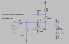
I am trying to make a time-varying gain amplifier for my ultrasonic receiver. I have chosen the VCA810 so far because I don't want to deal with feedback resistors and figuring out the gain-"control voltage" curves that seem to be there in other VGAs and I don't want to manually make voltage-controlled resistors with JFETs, or MOSFETs, etc.
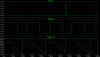
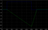
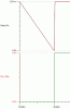
Now, I know I could use a DAC and an MCU to incrementally incrase the gain. Though I would prefer the gain to be contiously variable (otherwise I could have just used an op-amp with a serial-controlled digital pot rather than one of these VGA ICs). The gain control voltage has to go from 0V to -2V within a fixed time interval, except I'm not sure how to do this.
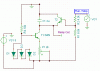
I was thinking a about using 555 timer circuit (or discrete comparators since the lower threshold voltage is different from that of a 555 timer and is inaccessible via the CONTROL pin), but the accurate capacitors are too small and result in resistor values that cause currents comparable to the input bias currents of the control voltage.
I am trying to make a time-varying gain amplifier for my ultrasonic receiver. I have chosen the VCA810 so far because I don't want to deal with feedback resistors and figuring out the gain-"control voltage" curves that seem to be there in other VGAs and I don't want to manually make voltage-controlled resistors with JFETs, or MOSFETs, etc.
Now, I know I could use a DAC and an MCU to incrementally incrase the gain. Though I would prefer the gain to be contiously variable (otherwise I could have just used an op-amp with a serial-controlled digital pot rather than one of these VGA ICs). The gain control voltage has to go from 0V to -2V within a fixed time interval, except I'm not sure how to do this.
I was thinking a about using 555 timer circuit (or discrete comparators since the lower threshold voltage is different from that of a 555 timer and is inaccessible via the CONTROL pin), but the accurate capacitors are too small and result in resistor values that cause currents comparable to the input bias currents of the control voltage.